Bios chipset setup screen, Figure 4-3 – ADLINK Express-HRR User Manual
Page 43
Chapter 4
BIOS Setup
Express-HRR
Reference Manual
39
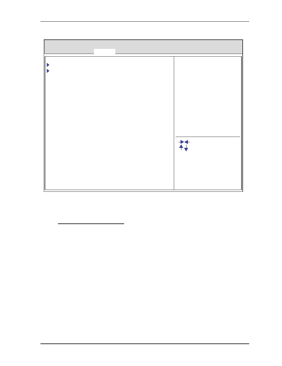
BIOS Chipset Setup Screen
Figure 4-3. BIOS Chipset Setup Screen
•
System Agent (SA) Configuration
♦
System Agent RC Version X.X.X.X
♦
VT-d Capability Supported
♦
VT-d [Disabled; Enabled]
♦
Graphics Configuration
•
IGFX VBIOS Version XXXX
•
IGFX Frequency XXX MHz
♦
Primary Display [Auto; IGFX; PEG]
♦
Internal Graphics [Disabled; Enabled]
♦
GTT Size [1MB; 2MB]
♦
Aperture Size [128MB; 256MB; 512MB]
♦
DVMT Pre-Allocated [0M; 32M; 64M; 96M; 128M; 160M; 192M; 224M; 256M; 288M; 320M;
352M; 384M; 416M; 448M; 480M; 512M]
♦
DVTM Total Gfx Mem [128M; 256M; MAX]
Express-HRR REV : XXX
Version X.XX.XXXX. Copyright (C) 20XX American Megatrends, Inc.
Express-HRR_BIOS_Chipset_a
Main Advanced Chipset Boot Security Save & Exit
System Agent (SA) Configuration
PCH-IO Configuration
[Setting Description]
: Select Screen
: Select Item
+/- : Change field
F1 : General Help
Enter : Select
F2 : Previous Values
F3&F9 : Optimized Defaults
F4 : Save & Exit
F10 : Save & Reset
ESC: Exit