Module type definition, Power and ground – ADLINK Express-IB User Manual
Page 30
Page 30
Express-IB
Signal
Pin
Description
I/O
PU/PD
Comment
PEG_TX15+
PEG_TX15-
D101
D102
AC coupled off Module
PEG_LANE_RV#
D54
PCI Express Graphics lane reversal input strap.
Pull low on the Carrier board to reverse lane order.
I 1.05V
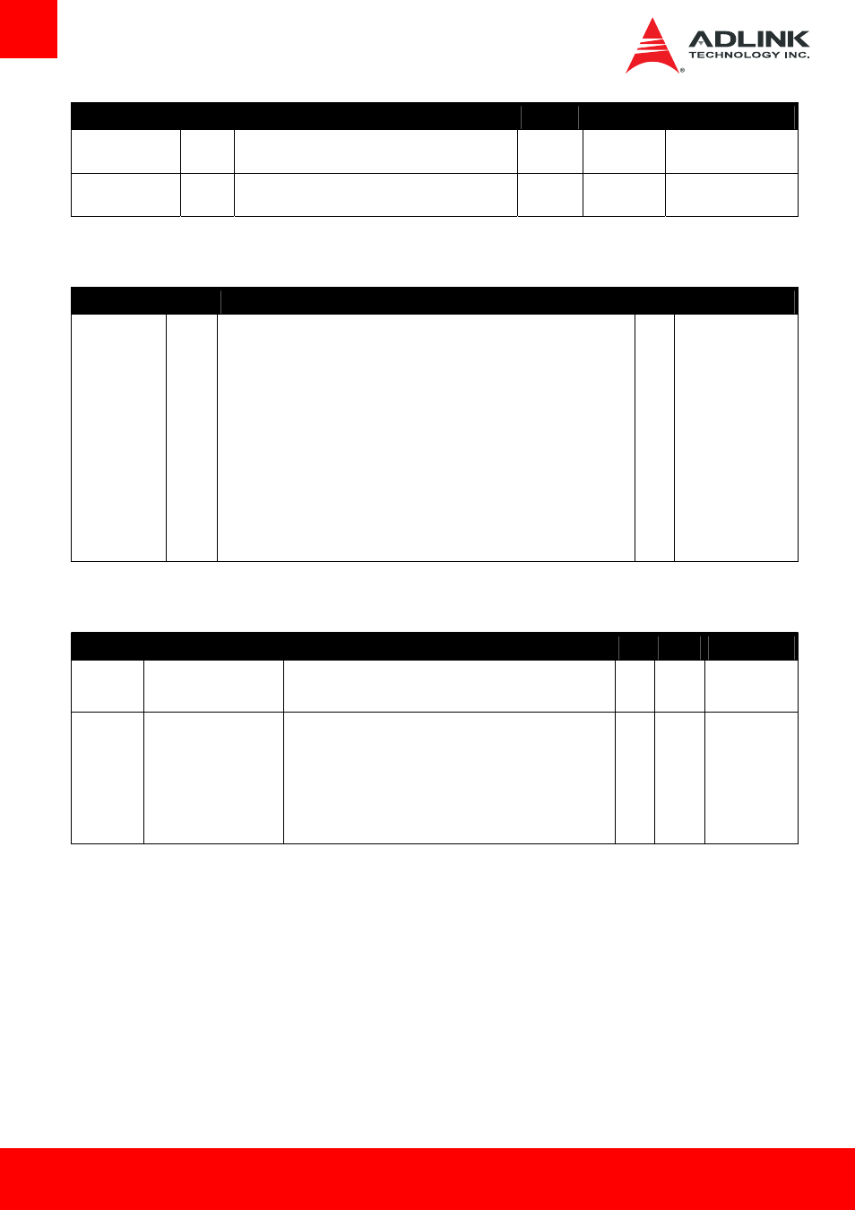
3.4.6. Module Type Definition
Signal
Pin #
Description
I/O
Comment
TYPE0#
TYPE1#
TYPE2#
C54
C57
D57
The TYPE pins indicate to the Carrier Board the Pin-out Type that is implemented on
the module. The pins are tied on the module to either ground (GND) or are no-
connects (NC). For Pinout Type 1, these pins are don’t care (X).
TYPE2# TYPE1# TYPE0#
X
X
X
Pinout Type 1
NC
NC
NC
Pinout Type 2
NC
NC
GND
Pinout Type 3 (no IDE)
NC
GND
NC
Pinout Type 4 (no PCI)
NC
GND
GND
Pinout Type 5 (no IDE, no PCI)
GND
NC
NC
Pinout Type 6 (no IDE, no PCI)
The Carrier Board should implement combinatorial logic that monitors the module
TYPE pins and keeps power off (e.g deactivates the ATX_ON signal for an ATX power
supply) if an incompatible module pin-out type is detected. The Carrier Board logic
may also implement a fault indicator such as an LED.
3.4.7. Power and Ground
Signal
Pin #
Description
I/O
PU/PD Comment
VCC_12V C104-C109
D104-D109
Primary power input: +12V nominal. All available VCC_12V pins on
the connector(s) shall be used.
P
8.5
~
19V
GND
C1, C11, C21, C31, C41,
C51, C60, C70, C76, C80,
C84, C87, C90, C93, C96,
C100, C103, C110, D1,
D11, D21, D31, D41, D51,
D60, D67, D70, D76, D80,
D84, D87, D90, D93, D96,
D100, D103, D110
Ground - DC power and signal and AC signal return path.
All available GND connector pins shall be used and tied to carrier
board GND plane.
P