4 operation theory, 1 i/o configuration, I/o configuration – ADLINK PCI-7300A User Manual
Page 43: Table 4-1: i/o configuration, 4operation theory
Operation Theory
31
4
Operation Theory
This chapter provides the detailed operation information for the
cPCI/PCI-7300A, including I/O configuration, block diagram, input/
output FIFO, bus-mastering DMA, scatter/gather, clocking mode,
starting mode, termination, I/O transfer mode, and auxiliary digital
I/O.
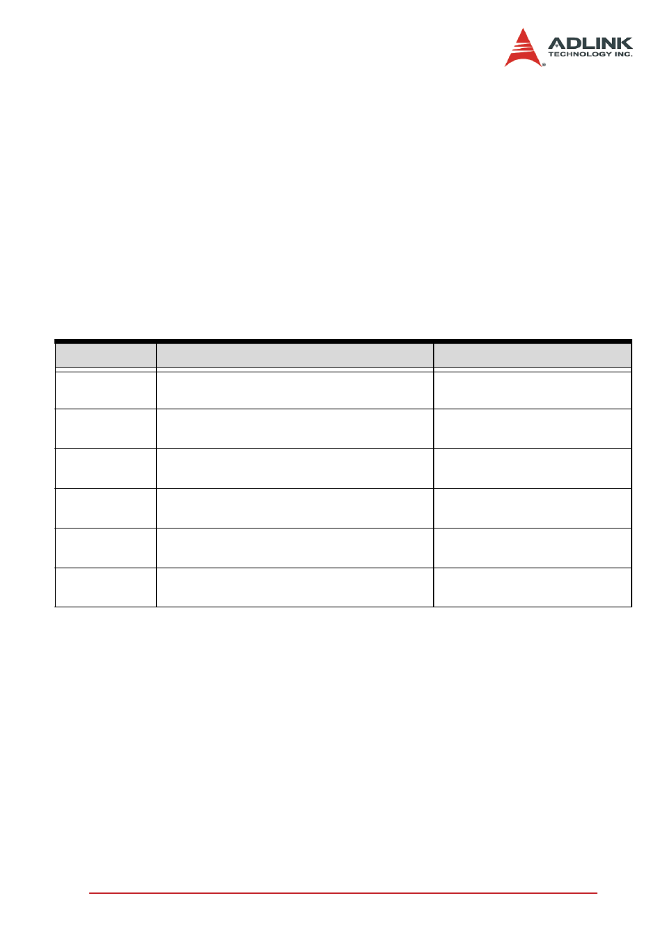
4.1 I/O Configuration
The 32-bit I/O data path of PCI-7300A can be configured as 8-bit,
16-bit, or 32-bit, the possible configuration modes are listed as fol-
lows.
Note:
X
PORTA is default as Input channel; PORTB is default as
output channel.
X
In DI32 mode, the PORTB has to be configured as the
extension of PORTA, that is, PORTB is the input port
(DI16…DI31). PORTB control signals are disabled.
X
In DO32 mode, the PORTA has to be configured as the
extension of PORTB, that is, PORTA is the output port
(DO16…DO31). PORTA control signals are disabled.
X
DI0: input LSB, DI31: input MSB;
Mode
Channel
Description
DI32
PORTA (DI0…DI15)
PORTB (DI16..DI31)
Both PORTA and PORTB are
configured as input channel
DO32
PORTA (DO16…DO31)
PORTB (DO0…DO15)
Both PORTA and PORTB are
configured as output channel
DI16DO16
(default mode)
PORTA (DI0…DI15)
PORTB (DO0…DO15)
PORTA is 16-CH input
PORTB is 16-CH output
DI16DO8
PORTA (DI0…DI15)
PORTB (DO0…DO7)
PORTA is 16-CH input
PORTB is 8-CH output
DI8DO16
PORTA (DI0…DI7) PORTB (DO0…DO15)
PORTA is 8-CH input
PORTB is 16-CH output
DI8DO8
PORTA (DI0…DI7) PORTB (DO0…DO7)
PORTA is 8-CH input PORTB
is 8-CH output
Table 4-1: I/O Configuration