5 double buffer mode principle, Figure 5-1: double buffer mode, 5double buffer mode principle – ADLINK PCIe-7200 User Manual
Page 48
Double Buffer Mode Principle
39
5
Double Buffer Mode Principle
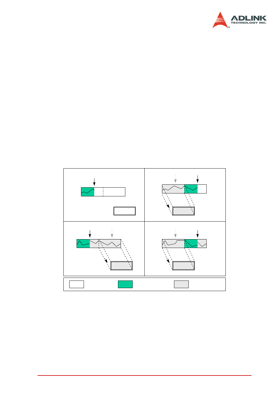
The data buffer for a double-buffered DMA DI operation is logically
a circular buffer divided into two equal halves. The double buffered
DI begins when the device starts writing data into the first half of
the circular buffer (Figure 6-1a). After device begins writing to the
second half of the circular buffer, users can copy the data from the
first half into the transfer buffer (Figure 6-1b). Users can now pro-
cess the data in the transfer buffer according to application needs.
After the board has filled the second half of the circular buffer, the
board returns to the first half buffer and overwrites the old data.
Users can now copy the second half of the circular buffer to the
transfer buffer (Figure 6-1c). The data in the transfer buffer is
again available for process. The process can be repeated end-
lessly to provide a continuous stream of data to applications (Fig-
ure 6-1d).
Figure 5-1: Double Buffer Mode
Incoming DMA
input data
Circular Buffer
Transfer Buffer
a
b
c
d
> > >
> > >
> >
Empty Buffer
Untransferred Data
Transferred Data
> >