6 connector pin assignments, Pci/pcie-7200 pin assignments, Connector pin assignments – ADLINK PCIe-7200 User Manual
Page 26
Installation
17
2.6
Connector Pin Assignments
PCI/PCIe-7200 Pin Assignments
The PCI/PCIe-7200 comes equipped with one 37-pin D-Sub con-
nector (CN2) located on the rear mounting plate and one 40-pin
female flat cable header connector (CN1). The CN2 is located on
the rear mounting plate; the CN1 is on front of the board. Refer
section 2.4 PCI-7200‘s layout.
CN2 is used for digital inputs (DI 0 to DI 15) and digital outputs
(DO 0 to DO 15) The reminding digital I/O channels DI 16 to DI 31
and DO 16 to DO 31 are on CN1. The pin assignment of CN1 and
CN2 is illustrated in the Figures 2-5 and 2.3.
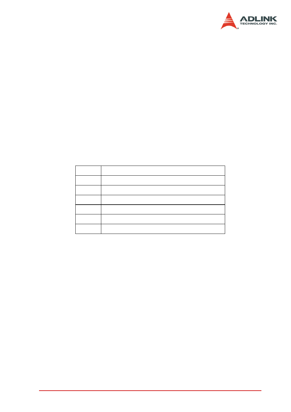
Legend:
DO n
Digital Output CH n
DI n
Digital Input CH n
GND
Ground
ACK
ACK handshaking signal
REQ
REQ handshaking signal
I_TRG
Input signal to start DI data sampling
O_TRG Output signal can be controlled by software
- USB-1901 (84 pages)
- USB-1210 (54 pages)
- USB-2401 (60 pages)
- USB-7230 (50 pages)
- USB-2405 (56 pages)
- DAQe-2010 (92 pages)
- DAQe-2204 (100 pages)
- DAQe-2213 (94 pages)
- DAQe-2501 (74 pages)
- PXI-2010 (84 pages)
- PXI-2020 (60 pages)
- PXI-2501 (62 pages)
- cPCI-9116 (98 pages)
- ACL-8112 Series (93 pages)
- ACL-8112 Series (94 pages)
- ACL-8112 Series (92 pages)
- ACL-8216 (75 pages)
- ACL-8111 (61 pages)
- PCM-9112+ (10 pages)
- PCM-9112+ (94 pages)
- cPCI-6216V (47 pages)
- ACL-6126 (28 pages)
- ACL-6128A (40 pages)
- PCM-6308V+ (52 pages)
- PCM-6308V+ (4 pages)
- PCI-7444 (82 pages)
- PCI-7434 (48 pages)
- PCI-7234 (56 pages)
- PCI-7260 (66 pages)
- PCI-7258 (38 pages)
- PCI-7256 (48 pages)
- PCI-7250 (48 pages)
- LPCI-7250 (48 pages)
- PCI-7396 (65 pages)
- PCI-7296 (59 pages)
- PCI-8554 (67 pages)
- PCIe-7360 (94 pages)
- PCIe-7350 (86 pages)
- PCIe-7300A (114 pages)
- PCI-7300A (112 pages)
- PCI-7300A (83 pages)
- PCI-7200 (96 pages)
- cPCI-7300 (82 pages)
- cPCI-7300 (83 pages)