ADLINK PCI-7224 User Manual
Page 38
30
• Operation Theorem
4.3.2 IRQ Level Setting
There is only one IRQ level requested by this card, although it is a dual
interrupt system. The motherboard circuits will transfer INTA# to one of the
PC IRQ levels. The IRQ level is set by the PCI Plug and Play BIOS and
saved in the PCI controller. Users can obtain the IRQ level setting in software
library.
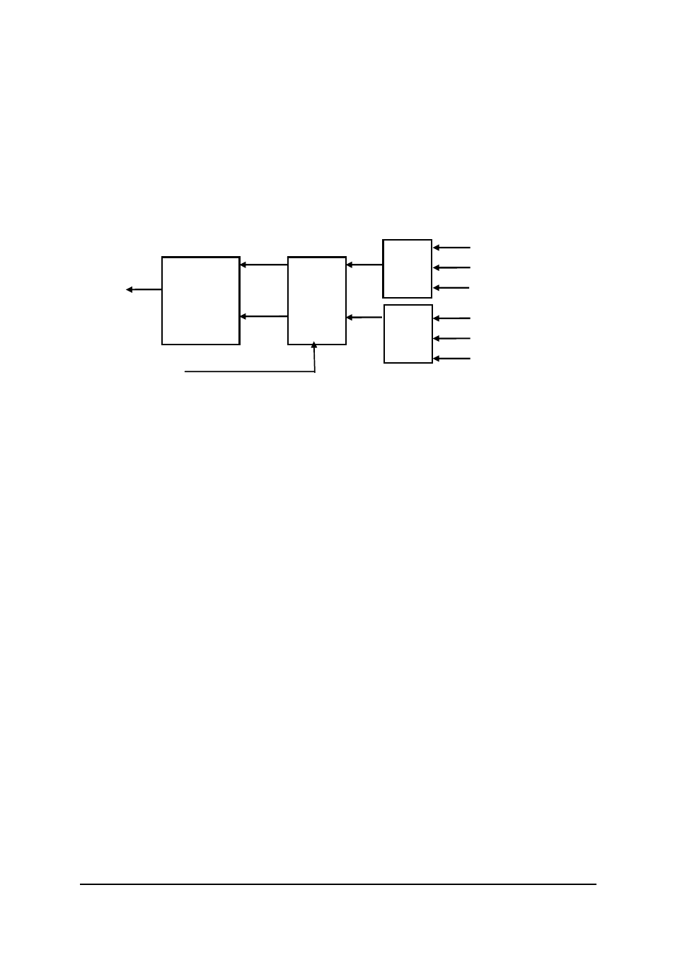
Fig 4.3 Dual Interrupt System of PCI-7224/7248/96
(*) Note: This interrupt is not available in PCI-7224
4.3.3 Note for Dual Interrupts
The PCI controller of PCI-7224/7248/96 can receive two hardware IRQ
sources. However, a PCI controller can generate only one IRQ to PCI bus,
the two IRQ sources must be distinguished by ISR of the application software
if the two IRQ are all used.
The application software can use the “_72xx_Get_Irq_Status” function to
distinguish which interrupt is inserted. After an ISR is completed, users must
check if another IRQ is also asserted, then clear the current IRQ to allow
room for the next IRQ.
The two IRQs are called INT1 and INT2. In PCI-7224/7248/7296, INT1
comes from P1C0, P1C3 or the event counter interrupt. INT2 comes from
P2C0, P2C3 or the timer interrupt. However in PCI-7224, INT2 only comes
from timer interrupt. The sources of INT1 and INT2 are selectable by the
Interrupt Source Control (ISC) Register.
PCI
Controller
INTA#
IRQ
Flip-
Flops
INT1
INT2
Clear IRQ
INT1
MUX
P1C0
~P1C0 & P1C3
Event Counter
INT2
MUX
P2C0 (*)
~P2C0 & P2C3 (*)
Timer IRQ