X x x ? ? ? x – ADLINK PCI-7224 User Manual
Page 34
26
• Operation Theorem
4.1.4 Digital I/O Port Programming
Users can write the digital output value to or read back the digital signal level
from the PPI ports by using the software library. The port names are defined
in Table 4.1. These port names are used throughout this manual as well as in
the software library. The programming for PCI-7224/7248/7296 and cPCI-
7248 are fully compatible.
Connector
Numbers
CN1 CN2 CN3 CN4
P1A P2A P3A P4A
Port P1B P2B P3B P4B
Names P1C P2C P3C P4C
P1CTRL P2CTRL P3CTRL P4CTRL
Table 4.1 I/O Port Names
There are four ports on every 8255 PPI, including ports A, B, C, and the
control port. PA, PB, and PC could be written or read but the control port is
write only. Refer to chapter 5 for more details on the programming of DIO
ports.
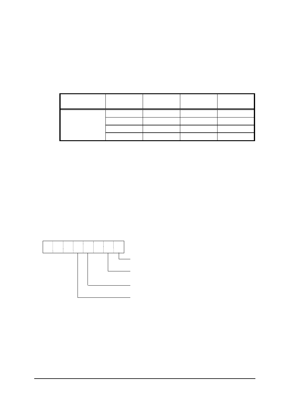
4.1.5 Control
Word
The control word written in the control port is used to setup PA, PB, and PC
as input or output port. Figure 4.1 shows the format of the control word. Table
4.2 shows the 16 possible control words and the respective I/O
configurations.
X X X ? ?
?
X
?
1/0 : Input/Output of Port C low nibble
D7 D6 D5 D4 D3 D2 D1 D0
1/0 : Input/Output of Port B
1/0 : Input/Output of Port C high nibble
1/0 : Input/Output of Port A
X : don't care
Figure 4.1 Control Word Format