ADLINK ACL-8216 User Manual
Page 48
40 • Operation Theorem
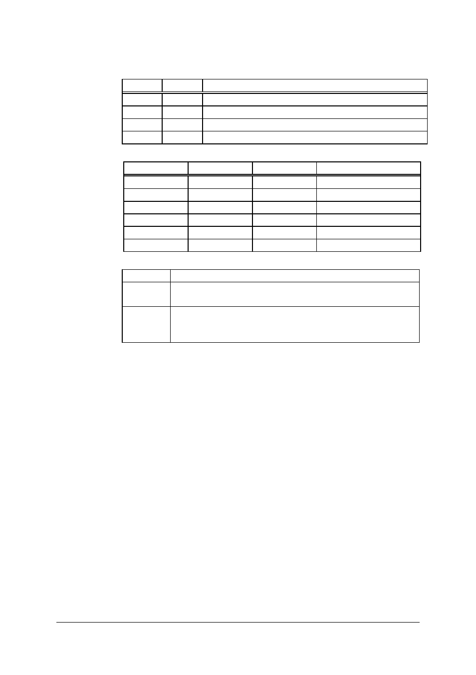
• RL1 & RL0 - Select Read/Load operation ( Bit 5 & Bit 4)
RL1 RL0 OPERATION
0
0
COUNTER LATCH FOR STABLE READ
0 1 READ/LOAD
LSB
ONLY
1 0 READ/LOAD
MSB
ONLY
1
1
READ/LOAD LSB FIRST, THEN MSB
• M2, M1 & M0 - Select Operating Mode ( Bit 3, Bit 2, & Bit 1)
M2 M1 M0 MODE
0 0 0 0
0 0 1 1
x 1 0 2
x 1 1 3
1 0 0 4
1 0 1 5
• BCD - Select Binary/BCD Counting ( Bit 0)
0
16-BITS BINARY COUNTER
1
BINARY CODED DECIMAL (BCD) COUNTER (4
DIGITAL)
Note
The count of the binary counter is from 0 up to
65,535 and the count of the BCD counter is from 0
up to 9,999
Mode Definitions
In 8254, six operating modes can be selected. they are:
• Mode 0: Interrupt on Terminal Count
• Mode 1: Programmable One-Shot.
• Mode 2: Rate Generator.
• Mode 3: Square Wave Rate Generator.
• Mode 4: Software Triggered Strobe.
• Mode 5: Hardware Triggered Strobe.
All detailed description of these six modes are written in Intel Microsystems
Components Handbook Volume II Peripherals.