Wiring power supply adaptor, Wiring door release el-9s, Installation of optional extension chime: ibrtq – Aiphone IBG-2AD User Manual
Page 3: Adjusting chime call tone volume ), Wiring diagram
Attention! The text in this document has been recognized automatically. To view the original document, you can use the "Original mode".
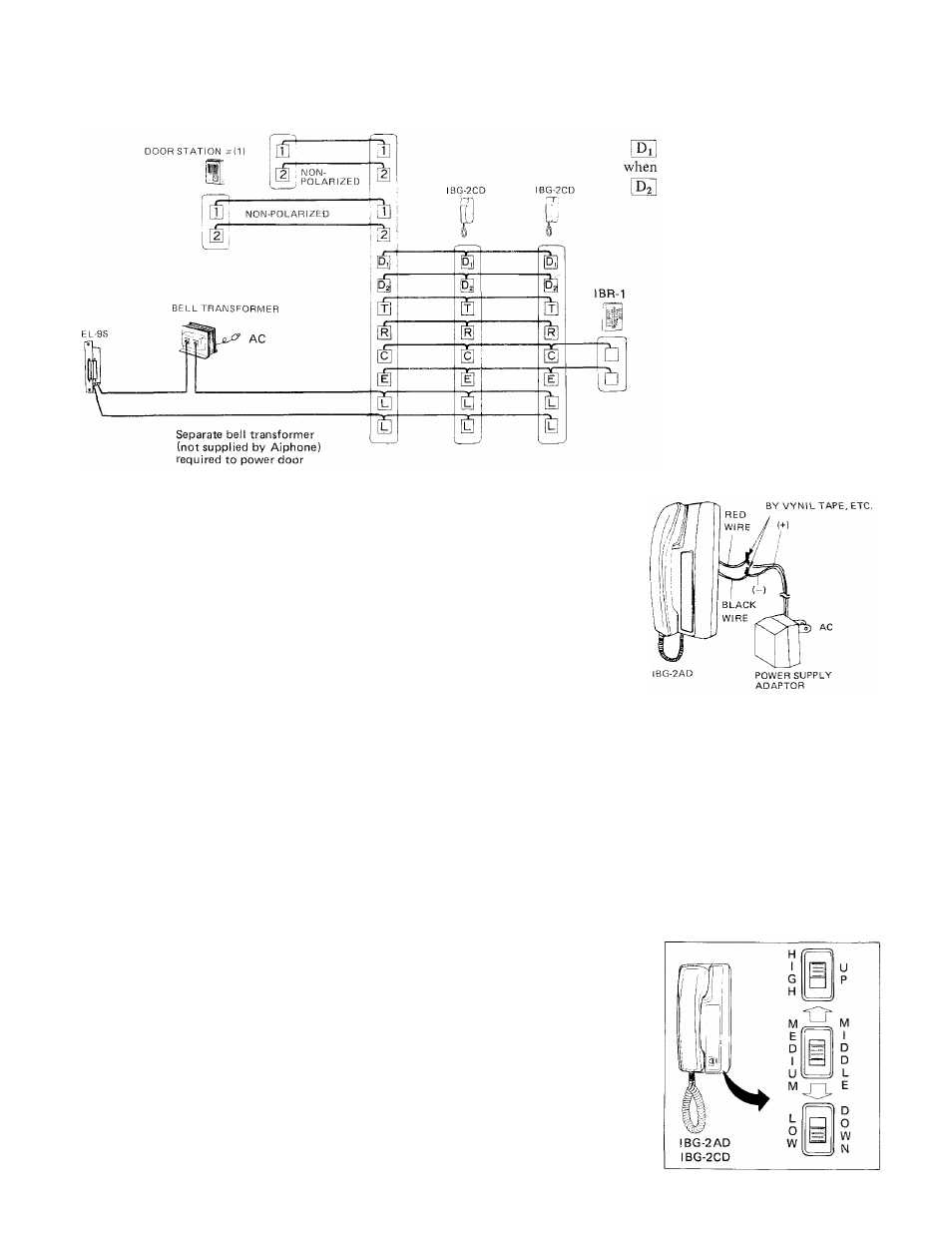
WIRING DIAGRAM
COMPLETE IBG-2AD SYSTEM
DOOR STATION #(2)
liH
MASTER
STATION
IBG-2AD
POWER SUPPLY
NOTE:
terminals may remain unused
terminals may remain unused
when door station # (2) is not connected.
release.
WIRING POWER SUPPLY ADAPTOR
Connect RED wire on back of IBG-2AD master to Plus (+) v^ire of power
supply adaptor.
Connect BLACK wire on IBG-2AD to Minus (—) wire of power supply adaptor.
Secure insulation at the junction part by vynil tape, etc., otherwise power supply
adaptor will be damaged.
WIRING DOOR RELEASE EL-9S^
SECURE INSULATION
* Separate bell transformer (AC 12V, 0.2A or more) is required to power EL-9S door release.
* Wiring for door release should be SEPARATED from wiring for communication (DO NOT RUN THEM IN THE SAME
CONDUIT).
* Attach two wires from terminals [I] , [l^ on room station to EL-9S as shown.
NOTE: Your IBG-2AD chime intercom will operate other brands of door releases. It is recommended they do not exceed
50V, lA.
INSTALLATION OF OPTIONAL EXTENSION CHIME: IB
r
TQ
Aiphone offers IBR-1 optional device for signaling chime call from door to a place remote from room station.
A reply from IBR-1 can not be made.
* Wiring: Attach two wires from terminals
on either IBG-2AD or IBG-2CD room station to IBR-1 call extension.
NOTE: One IBR-1 may be used per system.
( ADJUSTING CHIME CALL TONE VOLUME )
Chime call tone volume may be adjusted to three levels by setting switch as
desired.
NOTE: The volume switch also adjusts room station call tone at the same time,
while the chime call tone at IBR-1 remains unchanged.
3 -