Mounting and connection, Settings, Adjustments – Aiphone JDW-C User Manual
Page 2: Mounting and connection settings
Attention! The text in this document has been recognized automatically. To view the original document, you can use the "Original mode".
®AIPHONE‘
AlPHONE CO., LTD., NAGOYA, JAPAN
AlPHONE CORPORATION, BELLEVUE, WA, USA
AlPHONE S.A., WISSOUS, CEDEX, FRANCE
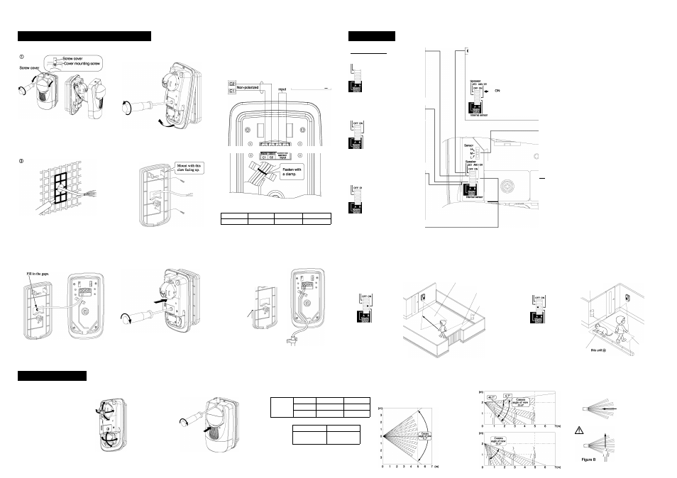
MOUNTING AND CONNECTION
SETTINGS
Remove the screw cover and loosen the cover mounting screw.
Pull the top of the two sides of the main unit cover toward you
and remove the main unit eover.
pA CAUTION--------------------------------------------
Do not pull the cover out more than is necessary.
It may result disconnection at cable.
When mounting on an outside wall with a large gap or on
an uneven surface, such as tiles, fill in the mounting surface
grooves and gaps with caulk.
pA CAUTION--------------------------------------------
If the waterproofing is incomplete, this can cause
equipment breakdown, fire, or electric shock.
Connect the necessary wires.
18 See the "Wiring diagram".
After that, fill in the gap at the wiring hole section.
@
Loosen the lock screw, pull the main unit bottom toward
you, and remove the main unit from the mounting plate.
Tear the wall sponge at the mounting plate wiring hole
section and pull the wires through from inside the wall.
Mount the mounting plate at the prescribed position.
18 Caulk around the wires before mounting the main unit.
Mount the unit onto the frame, then tighten down the lock
screws.
Next, adjust the ceimera and sensor.
For details, refer to "ADJUSTMENTS".
♦ Wiring
► Speaker switching
A
caution
----------------------------------
Always cut off the power switch before
wiring. Do not install with wet or damp
hands .Electric shock could result.
External
sensor
A
caution
----------------
Before turning on the
power, make sure wires
are not wrongly
connected or shorted.
Fire or electric
shock could result.
IW
p
I
^--
I---1__ I
—1
Wire the master station with PE (polyethylene) insulated wire with PVC jacket.
Refer to the table below for wire diameters and permitted wiring distances.
Singie core wire 0 0.65 mm
0 0.9 mm
0 1.2 mm
Distance
50 meters max.100 meters max.100 meters max.
Peel approx. 7 mm of insulation off the ends of wires.
Approx. 7 mm
♦ When surface cable runs are necessary
Mounting plate
Cut out the knockout at the bottom of the mounting plate and wire the
required wires to the main unit side.
Speaker
LED AND/OR
OFF ON
Make sure the speaker select switch is
always on "OFF" side.
Internal sensor
I Internal sensor switching
Speaker
LED AND/OR
Internal sensor
The internal sensor can be switched
ON/OFF by the main unit's internal
sensor select switch.
Use this when the internal sensor is
not necessary, for example when
using an external sensor.
The factory setting is "ON".
ON: The internal sensor
detects people.
OFF: The internal sensor does
not detect people.
B Operation indicator iight (LED) switching
The operation indicator light select switch can switch
the operation indicator lights ON/OFF. The normal
setting is "OFF". Switchmg OFF the operation indicator
light avoids making visitors aware that they are being
photographed by the camera.
The factory setting Is "OFF"
The LED lights up when
a person Is detected. It
lights up for approx. 2
sec. (Used for area
adjustment.)
OFF: The LED does not light
up. (This is the normal
position for use.)
I Master station switching
Speaker
'
led
and
/
or
You can switch the master station
version.
The factory setting Is "B".
B: JA series
Internal sensor
MIc. sensitivity
Low^*^HIgh
I Externai sensor input function
I Sensor sensitivity switching
The sensor sensitivity select switch can switch the
sensitivity with which people are detected among three
levels. Set this switch to match the enviromnent.
Sensor
M-
l
/
The factory setting Is "M"
H (High):
This raises the
sensitivity. (Set this If
detection is difficult.
M (Medium): Normally, use this
position.
' L (Low):
This lowers the
sensitivity. (Set this If
the system is
frequently triggered by
mistake.)
18 This does not change the sensitivity of a sensor cotmected
directly to the external sensor input.
A
The sensor sensitivity varies with the temperature
and this can cause mistaken detection. Set the
sensitivity according to the season as follows.
Summer-> H (High) Spring, Autuum (Medium) Winter-> L (Low)
I Mie. sensitivity
The internal mic. enables the user to hear outside
sounds from the master station. The volume can be
adjusted with the mic. sensitivity volume.
Mic. sensitivity
I WW
lj
-
u
Low^fe^High
The factory setting Is "Medium"
High: Raises the volume.
Low: Lowers the volume.
The external sensor input function coimects a separate sensor to this unit's external sensor input to widen the
detection range and improve the reliabihty of detection performance. For the external sensor unit, connect one
with N.C. type (normally closed) output.
The factory setting Is © set.
© OR mode
When a person enters the detection area of this unit or external sensor, the sensor detects this and their picture
is taken.
Since this mode is triggered by entry to either one of the detection areas, it can widen the detection area.
When not connecting an external sensor, set to this position.
Speaker
led
and
/
or
Detection area for this unit®
External sensor
detection area(g)
External sensor
Internal sensor
: The person is detected and photographed.
: The person is detected and photographed.
18 When connecting an external sensor, install it somewhere that the camera on this unit can photograph
anyone who enters that external sensor's detection area.
18When not connecting an external sensor, use "OR mode".
@ AND mode
If someone is detected by either this unit or the external sensor, then is detected by the other sensor within 30
sec., that person is detected and photographed.
(If someone passes through only one detection area, even if he/she then passes through the other detection area
more than 30 sec. later, he/she is not detected.)
Since the detectors do not detect if a person, a cat, or whatever passes through only one of the detection areas,
this is an effective measure against mistaken detection.
Speaker
LED AND/OR
External sensor
Internal sensor
(a) and ® : The person Is detected and photographed,
only (i), or only ® : Does not detect.
Detection area for
External sensor
detection area (E
ADJUSTMENTS
©Adjusting the camera direction:
The camera moves 50° to the left and to the right.
(It moves in 5° by a step.)
The camera moves 35° down.
(It moves in 5° by a step.)
©Adjusting the sensor direction:
The sensor moves 50° to the left and to the right.
(It moves in 10° by a step.)
The sensor moves 35° down.
(It moves in 5° by a step.)
ACaution:
Adjust the sensor direction with holding the
plastic knob on the top of the sensor, NOT with
touching the reflector plate or P.C. board of the
sensor. Touching the sensor with wet or damp
hands, could cause malfunction or breakdown.
©When the camera and
sensor adjustments are
complete, put the main unit
cover on securely from the
front and tighten down the
main unit cover mounting
screws.
♦Detection area and camera angle of view
Angle
adjustment
range
Left/right
Up/down
Camera
50° (5° increments) 35° (5° increments)
Sensor
50° (10° increments) 35° (5° increments)
Camera
angle of view
Horizontal angle of view
Vertical angle of view
71.5°
53.4°
Plain diagram
(0° left-right swing)
czz Sensor detection area
Side diagram
(up/down swing 0°)
CZ
2
Sensor detection area
Side diagram
(downward swing 25°)
czz Sensor detection area
♦installation precautions
Figure A
Sometimes a person
approaching the detection
area from directly in front
of the camera is difficult
to detect. (Figure A)
Mount so that persons
cut across the detection
area. (Figure B)