Piezoelectric igniter system – A.O. Smith Water Heater User Manual
Page 28
Attention! The text in this document has been recognized automatically. To view the original document, you can use the "Original mode".
7. Reconnect the igniter wire.
8. Turn gas supply on and refer to the Lighting Instruc
tions.
9. With the burner lit, check the gas control valve/
thermostat supply line, two piece wire connector,
manifold tube, and pilot tube connections for
leaks. Check for leaks by brushing on an approved
noncorrosive leak detection solution. Bubbles forming
indicate a leak. Correct any leak found. IMPORTANT:
All leaks must be fixed immediately.
10. Replace the outer door.
Testing the Igniter System
FLAME ARRESTOR BRACKET
DOOR GASKET
FIGURE 30.
MANIFOLD TUBE
FIGURE 31.
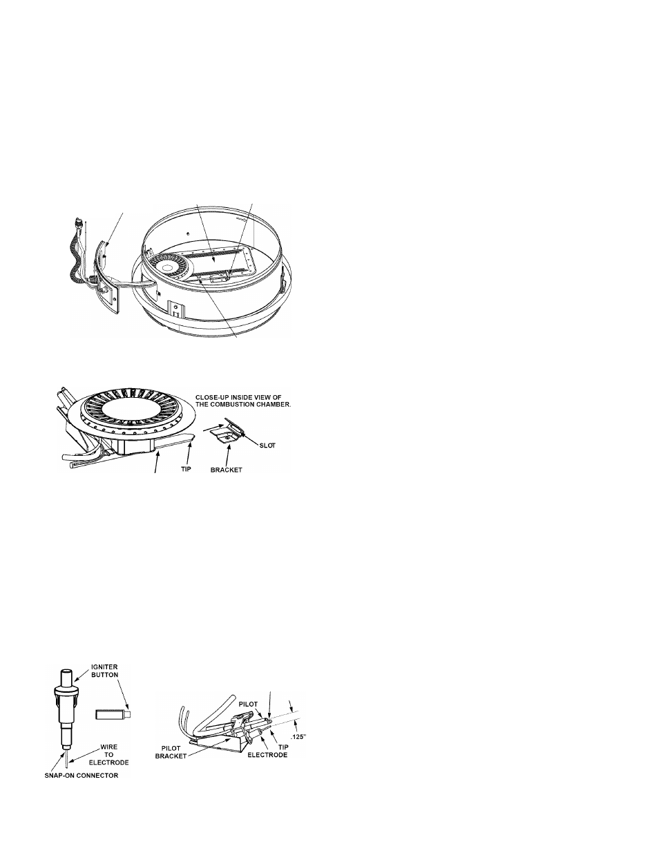
Piezoelectric Igniter System
The piezoelectric igniter system consists of the igniter
button, electrode, and wire. The pilot is ignited by an
electric spark generated when the igniter button is
pressed. The spark gap of 0.125 inch is set when the
electrode is installed at the factory. (Figure 32 ). Use
only factory authorized piezoelectric igniter parts for
replacement.
THERMOCOUPLE
> NOTE: SPARK GAP DISTANCE MEASURED FROM ELECTRODE TIP TO PILOT.
FIGURE 32.
Turn off the gas to the water heater at the manual gas
shut-off valve. Watch the electrode tip while activating the
igniter. A visible spark should jump from the electrode. To
avoid shock, do not touch the burner or any metal part
on the pilot or pilot assembly. If no spark is visible, check
the wire connections and make sure the electrode is not
broken. Replace the igniter if defective. Dirt and rust on the
pilot or electrode tip can prevent the igniter spark. Wipe
clean with a damp cloth and dry completely. Rust can be
removed from the electrode tip and metal surfaces by
lightly sanding with an emery cloth or fine grit sandpaper.
Removing and Replacing the Gas Control
Valve/Thermostat
IMPORTANT: This water heater has a resettable thermal
switch installed. Do not attempt to disable or modify this
feature in any way. Use only factory authorized
replacement parts.
Removing the Gas Valve:
1. Turn off the gas supply to the water heater at the manual
gas shut-off valve. This valve is typically located beside
the water heater. Note the position of the shut-off valve
in the open/on position then proceed to turn it off (Figure
3).
2. On the lower front of the water heater locate the
gas control valve/thermostat (see Figure 23). Before
performing any maintenance, it is important to turn the
temperature dial on the gas control valve/thermostat to
its iowest setting.
3. On top of the gas control valve/thermostat turn the
gas control knob to the “OFF” position. NOTE: On the
Robertshaw gas control valve/thermostat the knob stop
must first be depressed before turning the gas control
knob. See Lighting Instructions on the water heater.
4.
Drain the water heater. Refer to the section of
“Draining and Flushing” section and follow the
procedure.
5. Disconnect the igniter wire from the igniter. NOTE:
There are two types of igniters. If you have the square
igniter, slide the igniter bracket backwards away from
the gas valve to remove it. If you have the round igniter,
first remove the igniter from the bracket by depressing
front and rear holding tabs and lift. Next remove igniter
bracket from the gas valve. Disconnect the thermocouple
(right-hand threads), pilot tube, and manifold tube at the
gas control valve/thermostat (Figure 22). NOTE: L.P.
gas systems use reverse (left-hand) threads on the
manifold tube.
6.
Refer to “Gas Piping” section (Figure 3) and disconnect
the ground joint union in the gas piping. Disconnect the
remaining pipe from the gas control valve/thermostat.
7. To remove the gas control valve/thermostat, thread a
correctly sized pipe into the inlet and use it to turn the gas
control valve/thermostat (counterclockwise.) Do not use
pipe wrench or equivalent to grip body. Damage may
result, causing leaks.
Do not insert any sharp objects into the inlet or outlet
connections. Damage to the gas control valve/thermostat
may result.
28