Bolens 19967-1 User Manual
Page 8
Attention! The text in this document has been recognized automatically. To view the original document, you can use the "Original mode".
FRONT SUPPORT CHANNF
CLEVIS PIN (E)
and
COTTER-
PIN (F) INSTAL
PIN (E)-^^-
/
CLEVIS PIN
if/
FIGURE 11
R.H. DRIVE MOUNTING BRKT.
-----HEX BOLTS
.r
(AE)
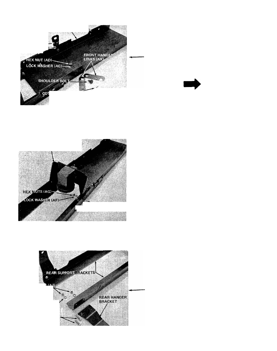
8. Assemble the front hanger links (AK) to the front
support channel. Insert shoulder bolt (AB) through
large hole on hanger links (AK), then through
the front support channel. Secure with lock
washer (AC) and hex nut (AD). See figure 11.
Insert clevis pin (F) through small hole in front
hanger links (AK) to hold them in position.
Secure with cotter pin (E). See figure 11. Cotter
pin and clevis pin will be removed later.
NOTE
Be sure hanger brackets swing freely
on shoulder bolt.
9. Secure right hand drive mounting bracket to rear
support angles with hex bolts (AE), lock washers
(AF) and hex nuts (AG). See figure 12. Tighten
securely.
FIGURE 12
HEX NU1
LOCK WASHERS
(All
HEX BOLTS (AH)
10.
Attach rear hanger brackets to rear support
brackets using hex bolts (AH), lock washers (Al)
and hex nuts (AJ). See figure 13. Tighten finger
tight only at this time.
FIGURE 13
8