Upflow, Furnace, D5 natural – Bryant Gas Fired Forced Air 394 User Manual
Page 2: 821/822 adjustable fan control, Upflow furnace, Del-iy, T ve, Figure 1 - control box, installed view, Both sides, Rmixal 'r - 3
Attention! The text in this document has been recognized automatically. To view the original document, you can use the "Original mode".
UPFLOW
FURNACE
Modet
No.
A.G.A. RATINGS BTU/HR
GAS CONNECTION
SIZES
Bottom
Filter
Sizes
Side
Filter
Sizes
Approx.
Shipping
Weight
Natural Propane
1 nput
Bonnet
Capacity
Input
Bonnet
Capacity
Natural
Propane
50-394
50,000
40,000
50,000
40,000
'Л
'/2
14 X 25 X 1
14 X 25 X 1
135
80-394
80,000
64,000
75,000
60,000
'/2
'/2
14 X 25 X 1
14 X 25 X 1
153
100-394
100,000
80,000
100,000
80,000
'/2
'/2
16 X 25 X 1
16 X 25 X 1
178
125-394
125,000
100,000
1 25,000
100,000
'/2
/2
20 X 25 X 1
20 X 25 X 1
200
1 37-394
137,500
11 0,000
Not available
'/2
'/2
20 X 25 X 1
20 X 25 X 1
202
165-394
165,000
132,000
150,000
120,000
'Л
’/2
(2) 14 X 25 X 1
(2} 16 X 25 X 1
282
190-394
190,000
152,000
175,000
140,000
'/2
'/2
0) 16 X 25 X 1
(1) 20 X 25 X 1
(2) 16 X 25 X 1
365
220-394
220,000
176,000
200,000
160,000
'/2
'/2
(1) 16 X 25 X 1
(1) 20 X 25 X 1
(2) 16 X 25 X 1
365
Model No.
A
В
C
D
E
F
G
H
J
К
L
M
N
P
R
s
T
50-394
46
26
16'/4
14=/8
20
%
2V,
4"
12/4
22%
l'/2
12
23
1
%
2
3%
*
333/8
80-394
46
26
16 1/4
14%
20
'/2
23/4
4"
12'/4
22
%
l
'/2
1
2
23
1
%
2
3%
*
333/8
1 00-394
46
26
18'/4
165/g
20
%
23/4
5"
14%
22
%
l
'/2
1 4
23
1
%
2
ЗУ2
*
335/8
125-394
46
26
20'4
18%
20
'/2
23/4
5"
18%
22
%
l
'/2
1
8
23
1
%
2
ЗУ2
*
33
%
137-394
46
26
20'A
18%
20
%
23/4
5"
18%
22%
l'/2
1 8
23
1
%
2
3V2
*
333/8
1 65-394
51
28У4
2 81/4
26%
173/4
2/2
5
6"
25%
23%
23/8
23
24
2
%
8%
4
30'3/4
190-394
51
283/4
36У,
34%
173/4
2
%
5
(2) 5" •
33%
23%
23/8
23
24
2
%
8%
4
30'3/i
220-394
51
283/4
361/4
343/s
173/4
2
%
5
(2) 5"
33%
23%
2%
23
24
2'/e
8У2
4
30'3/i
*Both Sides
be generated by the thermocouple and the 100% inline
shut-ofF valve will close. No gas can then flow to the
pilot.
D5 Natural
Should the pilot go out, no current will be generated
by the thermocouple and the pilot-relay will close,
shutting oiF the gas to the pilot, and breaking the elec
trical circuit to the Bryant automatic gas control valve.
821/822 Adjustable Fan Control
The Model 394 Furnace incorporates the 821/8.22
relay for fan control. (The 821 relay is used with the
643 gas valve on furnace sizes 50 through 165; the 822
relay is paired with the 641 valve on sizes 190 and 220.)
The 821/822 has a field-adjustable differential. The
“max off’ setting on the dial is for the longest “off’
time and shortest “on” time.
When facing the front of the furnace, the “off’ cycle
is lengthened by moving the adjustment lever to the
left. The “off’ cycle is shortened by moving the lever
to the right. The adjustment of the “off’ cycle has the
opposite effect on the “on” cycle; however, to a lesser
degree.
-RMiXAL 'R -
3^.
^ '»J
Ш 8?1. 622
^ T VE
DEL-iY
■ '!• PPI
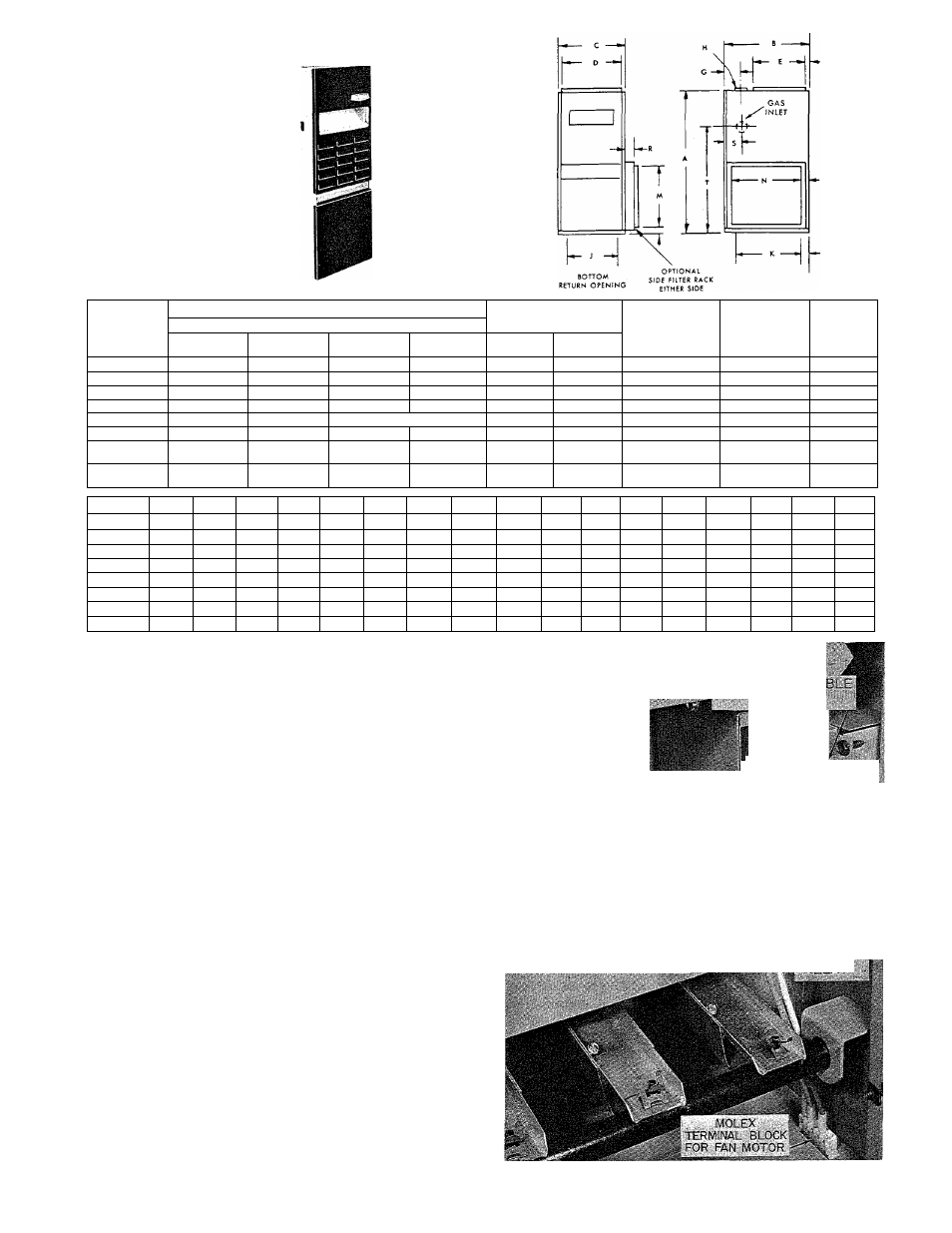
Figure 1 - Control Box, Installed View
39394D41