Gas piping – Bryant Gas Air 393U User Manual
Page 6
Attention! The text in this document has been recognized automatically. To view the original document, you can use the "Original mode".
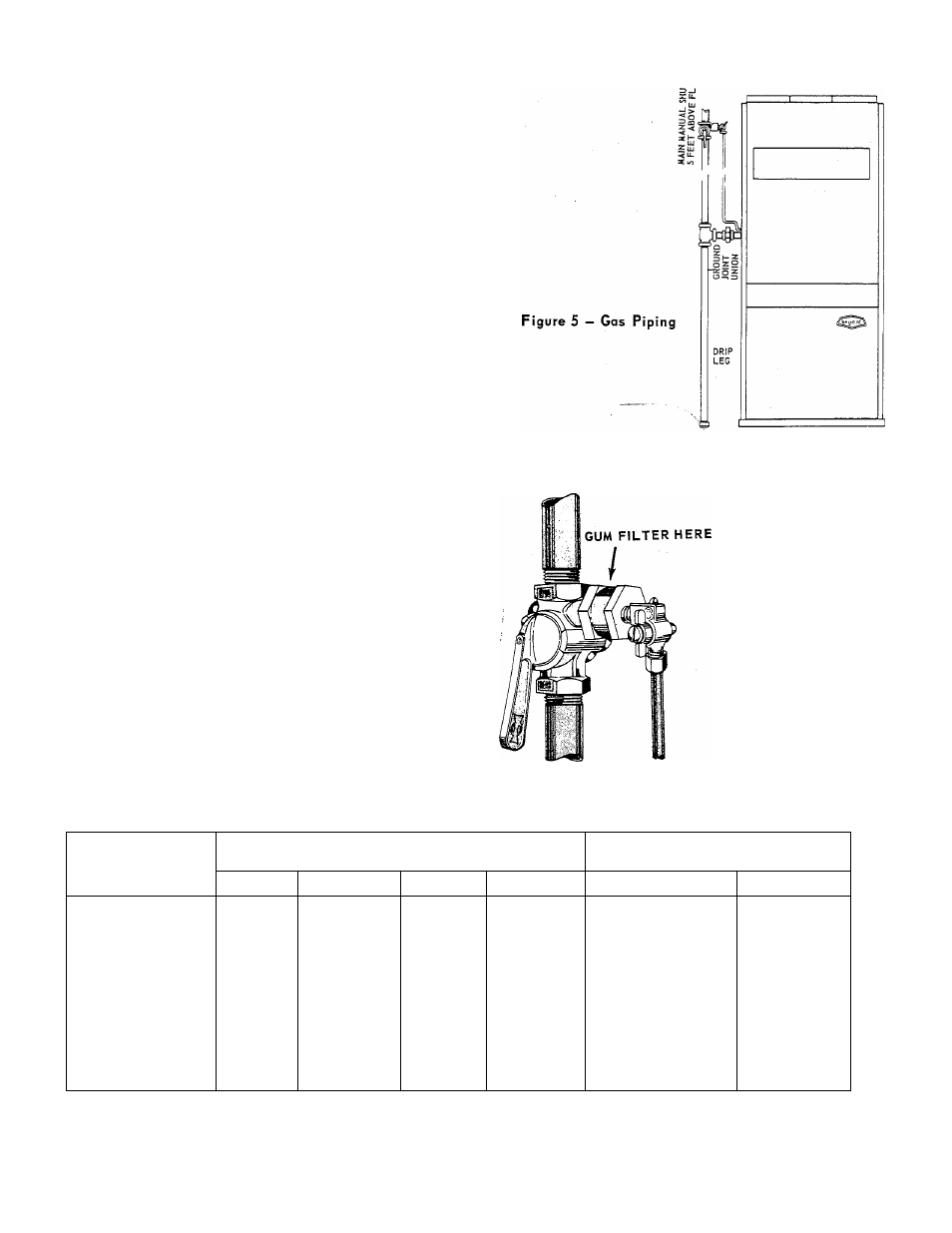
GAS PIPING
The gas supply line should be a separate line direct
from the meter to the furnace. Check local utility for
recommendations concerning existing lines. Choose
a supply pipe size large enough to keep the pres
sure loss as low as practicable. The supply pipe
should never be smaller than the inlet to the gas
valve. For pipe capacities at 0.3 inches w.c. pres
sure drop, see Iron Pipe Capacity table below.
Observe local codes for all gas pipe installation.
The following are pertinent recommendations:
1. Avoid low spots in long runs of pipe. These low
spots may trap water in the supply line. It is best
to slope all pipe 1/4 inch in 15 feet to prevent
traps. All horizontal runs should slope to risers.
Risers should be used to connect to the furnace and
to the meter.
2.
Install a drip leg in the riser leading to the
furnace. This drip leg will serve as a trap for dirt
or condensate.
This drip leg can be installed by connecting a TEE
to the riser leading to the furnace, so that the
straight-through section of the TEE is vertical.
Then connect a capped nipple to this TEE. The
capped nipple should extend below the level of the
gas controls, with the cap resting on the floor.
3. Install the main manual gas shut-off valve in the
supply line five feet above the floor. Install the
valve (supplied) so that the pilot manual cock is on
the inlet side of the valve. (See Figure 5.)
Figure 6
IRON PIPE CAPACITY (See Notes 1 & 2)
Length of Pipe
in Feet
Pipe Capacity in Cubic Feet Per Hour
for Diameters Shown
Multiplier to Use
for Different Specific Gravity
1/2"
3/4"
1"
1-1/4"
Specific Gravity
Multiplier
15
76
172
345
750
.35
1.31
30
52
120
241
535
.40
1.23
45
43
99
199
435
.45
1.16
60
38
86
173
380
.50
1.10
75
77
155
345
.55
1.04
90
70
141
310
.60
1.00
105
65
131
285
.65
.962
120
120
270
.70
.926
150
109
242
180
100
225
1. All values shown are based on a pressure drop of 0.3" w.c. and using gas with a specific gravity value
of 0.60 Consult local utility for local variations.
2. To convert to capacities for gas of different specific gravity, multiply the capacity values by the multi
pliers shown at the extreme right on table.
393U
- 6 -