Specifications-544b – Bryant 544B User Manual
Page 3
Attention! The text in this document has been recognized automatically. To view the original document, you can use the "Original mode".
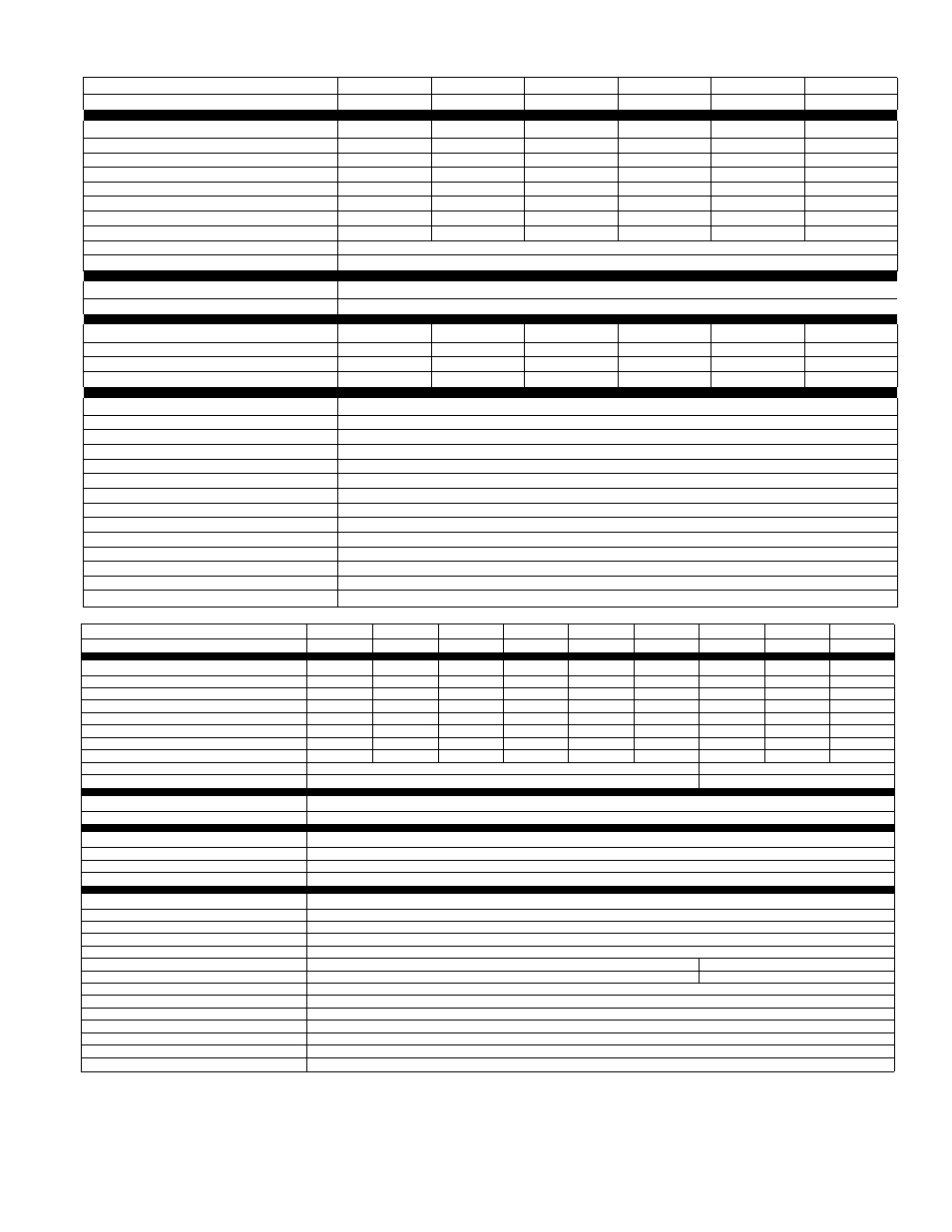
SPECIFICATIONS-544B
SIZE
018
024
030
036
036
036
SERIES
A
A
A
A
A
A
ELECTRICAL
Unit Volts—Hertz—Phase
208-230—60—1 208-230—60—1 208-230—60—1 208-230—60—1 208/230—60—3
460—60—3
Operating Voltage Range
197—253
197—253
197—253
197—253
187—253
414-506
Unit Ampacity for Wire Sizing
13.5
15.5
20.3
23.0
15.5
6.9
Min Wire Size (60 Copper) (AWG)*
14
12
10
10
12
14
Max Branch Circuit Fuse Size (Amps)
20
25
30
40
25
10
Total Unit Amps
11.0
12.6
16.4
18.6
12.6
5.6
Compressor Rated Load Amps
10.0
11.6
15.4
17.6
11.6
5.1
Locked Rotor Amps
49.0
54.0
69.0
88.0
65.1
32.8
Fan Motor, HP & Type
1/10 &PSC
Full Load Amps
TO I TO ^ TO I TO I TO I 05
COMPRESSOR AND REFRIGERANT •
Compressor
Hermetic
Refrigerant Charge
7 lbs—14 oz 1 7 lbs—10 oz 1 9lbs—Ooz | 11 lbs—8 oz
OUTDOOR COIL & FAN
Coil Face Area (Sq Ft)
11.5
11.5
14.3
17.2
17.2
17.2
Rows & Fins Per Inch
2&20
2 &20
2 &20
2&20
2&20
2&20
Fan Diameter & No. of Blades
22 &3
22 &3
22 &3
22 &3
22 &3
22 &3
Rated Airflow (Cfm)
2300
2300
2300
2300
2300
2300
OPTIONAL EQUIPMENT
Room Thermostat w/Auto Changeover
P271-3456
Room Thermostat w/Manual Changeover
P271-3457
Room Thermostat—Night Set-Back
P271-3471
Unit Mounting Base
301392-702
High-Pressure Switch
309914-701
Indoor Fan Time Delay Relay
309919-701
Thermal Expansion Valve Kit
Standard
Quick-Start Capacitor-Relay Kit
309917-701
2-Way Flow Filter-Drier—Liquid Tube
301399-701
Filter-Drier—Vapor Tube
P501-8031
Outdoor Thermostat and Mtg Bracket
310527-701
COMPROTEC
309915-701
Defrost Solenoid Kit
311765-751
Swivel Ells—Liquid/VaporTubes
P651-1066/P651-1068
SIZ E
042
042
042
048
048
048
060
060
060
SERIE S
A
A
A
A
A
A
A J
A
A
1 ELECTRICAL
.
Unit Volts—Hertz—Phase
208-230-60-1
208/230-60-3
460-60-3
208-230-60-1 208/230-60-3
460-60-3
208-230-60-1
208/230-60-3
460-60-3
Operating Voltage Range
197-253
187-253
414-506
197-253
187-253
414-506
197-253
187-253
414-506
Unit Ampacity for Wire Sizing
27.5
17.6
8.3
30.8
19.5
9.3
38.8
25.7
13.7
Min Wire Size (60 Copper) (AWG}*
10
12
14
8
14
14
8
10
12
Max Branch Circuit Fuse Size (Amps)
45
30
10
50
30
15
60
40
20
Total Unit Amps
22.2
14.3
6.7
24.8
15.8
7.5
31.5
21.0
11.2
Compressor Rated Load Amps
21.2
13.3
6.2
23.8
14,8
7.0
29.2
18.7
10.0
Locked Rotor Amps
108.0
74.0
37.0
116.0
92.0
46.0
135.0
105.0
55.0
Fan Motor, HP & Type
1 1/10&PSC ¡
1 1/3&PSC 1
Full Load Amps
1____ _______ 1
_____L?_____ 1
0.5 1____________ 1____________ 1
0.5 i1____2,3____ 1
2.3 I_____L2____
1
COMPRESSOR AND REFRIGERANT
Compressor
1 Hermetic
Refrigerant Charge
14 lbs—5 oz
1
13 lbs—0 oz
15 lbs—8 oz
1
OUTDOOR COIL & FAN
Coil Face Area (Sq Ft)
22.9
22.9
22.9
22.9
22.9
22.9
! 22.9
22.9
22.9
Rows & Fins Per Inch
' 2 & 2 2
2 & 2 2
2 & 2 2
2 & 2 2
2 & 2 2
2 & 2 2
' 2 & 2 2
2 & 2 2
2 & 2 2
Fan Diameter & No. of Blades
22 &3
22 &3
22 &3
22 &3
22 &3
22 &3
22 &3
22 &3
22 &3
Rated Airflow (Cfm)
2300
2300
2300
2300
2300
2300
3500
3500
3500
OPTIO NAL E QUIPMENT
•
Room Thermostat w/Auto Changeover
P271-3456
Room Thermostat w/Manual Changeover
P271-3457
Room Thermostat—Night Set-Back
P271-3471
Unit Mounting Base
301392-702
High-Pressure Switch
309914-701
Indoor Fan Time Delay Relay
309919-701
1
309919-701
1
Standard
1
Thermal Expansion Valve Kit
Standard j
308791-751 1
Quick-Start Capacitor-Relay Kit
309917-701
2-Way Flow Filter-Drier—Liquid Tube
301399-701
Filter-Drier—Vapor Tube
P501-8032
Outdoor Thermostat and Mtg Bracket
310527-701
COMPROTEC
309915-701
Defrost Solenoid Kit
311765-751 I
Swivei Ells—Liquid/VaporTubes
P651-1066/P651-1068
*lf other than 60°C copper wire is used, size can be determined from unit ampacity given in above tabie and appiicabie tabie of Nationai Eiectric
Code. Wire size seiected must have current capacity not iess than that of copper wire specified and must not create a voitage drop between service
panei and unit in excess of 2% of unit rated voitage.
tThe factory refrigerant charge is sufficient for systems requiring up to 30-feet of interconnecting tubing. For tubing lengths other than 30-feet, see
Installation Instructions for additional refrigerant requirements.
iSingle-phase units may use fuses or HACR-type circuit breakers (U.S. only) of same size as noted.
HP-55