Throttle control installation, Note, Control rod installation and adjustment – MTD 215-386-000 User Manual
Page 7
Attention! The text in this document has been recognized automatically. To view the original document, you can use the "Original mode".
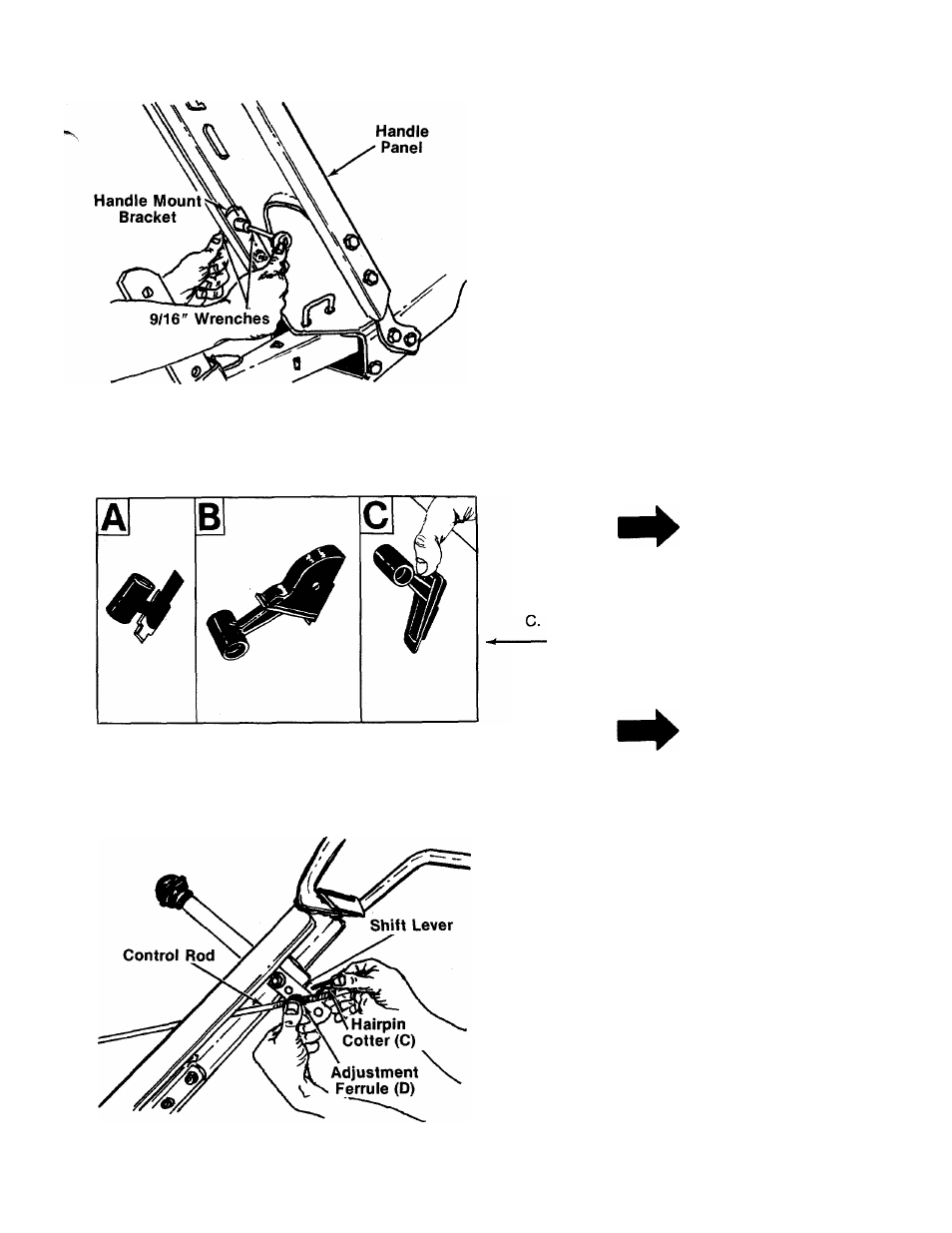
FIGURE 10.
FIGURE 11.
Secure handle panel with four hex bolts (L), lock
washers (N) and hex nuts (O). Lock washers and
hex nuts are tightened from the inside of handle
-panel. Tighten securely. See figure 10.
Slip hand grips on the upper end of each handle.
They will slip on more easily if you first soak them
in warm, soapy water.
6. Throttle Control Installation
Assemble the throttle control to the handle panel
as follows.
A. Hold the throttle control assembly beneath
the handle panel. Turn the control sideways
and insert the lever up through the wide por
tion of the slot on the handle panel.
B. After the end of the lever is through the slot,
turn and then tip the control forward as
shown in figure 11B to slide it through the
slot.
NOTE
The lever must be all the way to the
back of the control housing as
shown in figure
11
B.
Push the control back into the slot in the han
dle panel and press in place. Be certain the
control is locked securely into the slot.
7. Control Rod installation and Adjustment
B.
FIGURE 12.
NOTE
Changing the handle position re
quires readjustment of the clutch
rod.
A. Place shift lever in 1st speed position. Thread
ferrule up or down control rod so that ferrule
lines up with hole in shift lever. See figure 16.
Secure ferrule with flat washer (E) and hairpin
—cotter (C).
Put shift lever in neutral position. With the
spark plug grounded, pull starter cord several
times.
The tines should not turn.
If they do,
remove the hairpin cotter, flat washer and fer
rule. Thread the ferrule in or out as necessary.
Replace and check again for correct adjust
ment.
H^
note
If neutral cannot be obtained after
following above procedure several
times, refer to engine adjustment
section on page
11
.