Depth bar installation, Attaching handle mount brackets, Note – MTD 215-386-000 User Manual
Page 5
Attention! The text in this document has been recognized automatically. To view the original document, you can use the "Original mode".
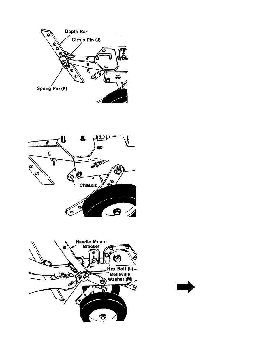
2. Depth Bar Installation
Slide the depth bar into the tailpiece to desired
depth. Secure with clevis pin (J) and spring pin (K).
■See figure 4.
FIGURE 4.
Three Handle
Mount Locations
Handle Mount
Brackets \
3. Attaching Handle Mount Brackets
For shipping purposes, the handle mounting
■ brackets are pivoted down. See figure 5. Pull han
dle mount brackets up and select height position
for the handle by lining up one of the holes in the
handle mount brackets with desired hole in
chassis. See figure 5.
FIGURE 5.
9/16" or
Adjustable Wrench
Place hex bolt (L) and belleville washer (M)
(cupped side against the handle mount bracket)
through handle mount bracket and chassis.
Secure with lock washer (N) and hex nut (O) on the
■inside of chassis. See figure
6
.
NOTE
This tiller is a variable speed unit.
Any movement in the handle (after
assembly) may change your speed.
The handle mount brackets
must be
as tight as possible. See figure
6
.
FIGURE 6.