Wheel setting for deep digging, Note, Cultivating – MTD 215-386-000 User Manual
Page 10
Attention! The text in this document has been recognized automatically. To view the original document, you can use the "Original mode".
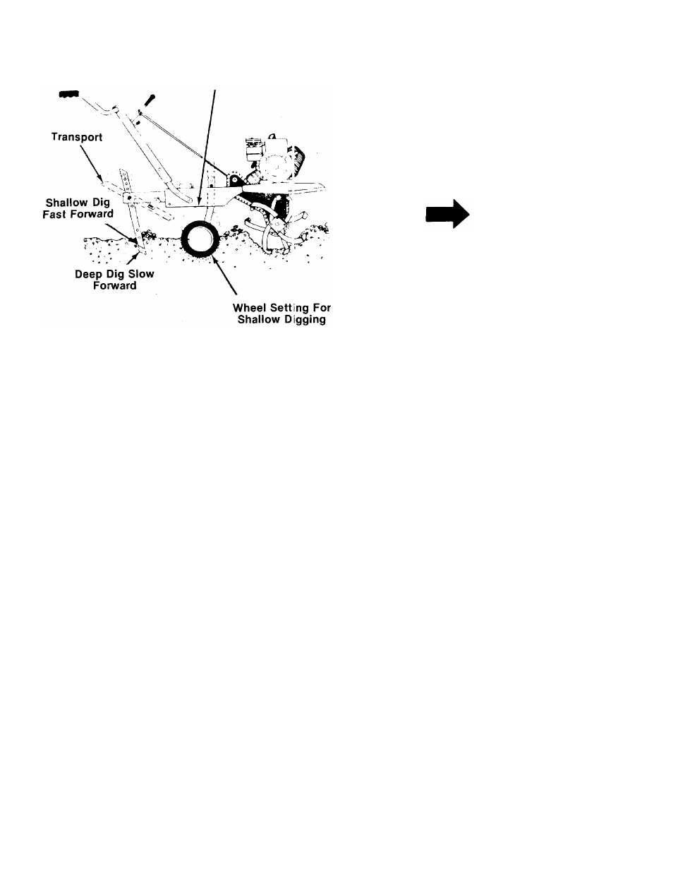
Wheel Setting
For Deep Digging
and/or Traisport
FIGURE 17.
By increasing the depth of the depth b ir, the
forward speed of the machine is reduced, and
the working depth is increased. When the
depth bar is raised, the working depth of the
machine is reduced and the forward speed is
increased. The working depth of the machine
may be predetermined by setting the depth
bar and wheels so that the wheels are about
four inches from the ground when the tines
and depth bar are resting on the ground. This
setting will permit a working depth of about
four inches. Use maximum engine speed for
deep tilling. When presetting the wirking
depth, the handles should be a little above
waist height because the tiller will be lower
when the tines and depth bar penetrate the
ground. The best method will be deternined
by the soil condition. In some soil:;, the
desired depth is obtained the first t i m j over
the garden. In other soils, the desired dc pth is
obtained by going over the garden two or
three times. In the latter case, the depth bar
should be lowered before each succeeding
pass over the garden. Passes should be made
across the length and width of the garden
alternately. Rocks which are turned up i hould
be removed from the garden area.
3.
Handle Pressure:
Further control of tilling
depth and travel speed can be obtair ed by
variation of pressure on the handles. A down
ward pressure on the handles will reduce the
working depth and increase the forward
speed. An upward pressure on the handles
will increase the working depth and reduce
the forward speed. The type of soil and work
ing conditions will determine the actual set
ting of the depth bar and the handle pressure
required.
4.
Throttle Control:
The throttle control lever is
iocated on the right side of handle panel.
NOTE
Right hand side is determined from
the
operator’s
position
standing
behind the tiller.
The throttle control lever adjusts the engine
speed. It also gives finger tip control of the car
buretor and magneto stop switch. With the throt
tle control knob pushed completely forward, the
carburetor is in “START” position. Pulling the
throttle control back slightly adjusts the engine
speed to “FAST.” Pulling the throttle back further
reduces the engine speed to “SLOW.” When the
throttle is pulled completely back, the magneto
stop switch grounds out the spark and stops the
engine. Use maximum engine speed for deep till
ing.
Move the throttle control to slow when transpor
ting the tiller. When the tiller is being moved to or
from the garden, the depth bar should be pivoted
forward until it engages the depth bar spring pin.
The machine may be moved under its own power,
without damaging grass areas as long as it is
allowed to move freely. If the operator holds back,
it will start to dig.
CULTIVATING
For cultivating, a two to three inch depth is
desirable. Setting the wheels and depth bar so
that the wheels are about two inches above the
ground while the tiller is resting on the tines and
depth bar will allow the machine to work at
cultivating depth. The throttle should be set to
control forward movement to a slow walking
speed. With standard tines, the maximum working
width of the tiller is 26 inches. This width may be
reduced to 24 inches by moving the clevis pins
and hairpin cotters to the inner holes on the tine
shaft. For cultivation, remove the outer tines to
obtain a tilling width of 13 inches.
When laying out plant rows, be sure to allow
enough width to permit cuitivation between the
rows. In growing corn or similar crops, check-row
planting will permit cross cultivation and prac
tically eliminate hand hoeing.
10