Note, Contents of hardware pack (see figure 2), Tailpiece installation – MTD 215-386-000 User Manual
Page 4: Assembly instructions
Attention! The text in this document has been recognized automatically. To view the original document, you can use the "Original mode".
Tiller
Hardware P ick
Depth Bar
FIGURE 1.
ASSEMBLY
INSTRUCTIONS
Handle
Panel Assembly
Tail Piece
Shift Lever
Control Ro J
FIGURE 2.
NOTE
This unit is shipped WITHOUT GAS
OLINE or OIL. After assembly, see
operating sectipn of this manual for
proper fuel and engine oil recom
mendations.
Before any step is undertaken, the instructions for
that step should be read thoroughly.
-Tools Required (See Figufe 1)
1. (1) V
2
" Socket, Open or Box Wrench
2. (2) 9/16" Socket, Open or Box Wrench
3. (1) V
4
" Flat Screwdriver
Parts in Carton (See Figure 1)
Tiller
Handle Panel Assembly
Depth Bar
Tailpiece
Control Rod
Hardware Pack
Shift Lever
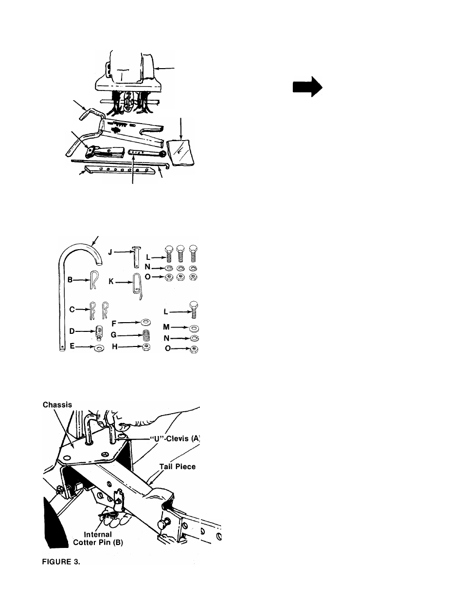
-Contents of Hardware Pack (See Figure 2)
A (1) “U”-Clevis Pin
B (1) Internal Cotter Pin
C (2) Hairpin Cotters
D (1) Adjustment Ferrule
E (1) Flat Washer 5/16" I.D.
F (1) Belleville Washer 5/16" I.D.
G 0) Compression Spring
H (1) Hex Lock Nut 5/16-18 Thread
J (1) Clevis Pin
K (1) Spring Pin
L (
6
) Hex Bolts 3/8-16 x 1.00" Long
M (2) Belleville Washers 3/8" I.D.
N (
6
) Lock Washers 3/8" I.D.
O (
6
) Hex Nuts 3/8-16 Thread
P (2) Hand Grips (Not Shown)
1. Tailpiece Installation
Slide the tailpiece into the chassie. Secure with
-“U”-Clevis (A) and internal cotter pin (B). See
figure 3.