Beam and splining wedge, Hose clamps, Engine – MTD 241-521-000 User Manual
Page 11: Flexible pump coupler, Tire pressure, Installation of tire to rim
Attention! The text in this document has been recognized automatically. To view the original document, you can use the "Original mode".
BEAM AND SPLiniNG WEDGE
Lubricate
both
sides
of
the
beam
where
it
contacts
the
splitting
wedge
with
engine
oil
before
each
use
to
ob
tain
years
of
service.
However,
normal
wear
will
occur.
The wedge plate on the log splitter is designed so the
gibs on the side of the wedge plate can be easily re
moved
and
rotated
and/or
turned
over
for
even
wear.
Make
certain
to
readjust
the
adjustment
bolts
so
wedge
moves
freely,
but
no
excess
space
exists
between
the
wedge plate and beam.
HOSE CLAMPS
Check
the
hose
clamps
on
the
suction
hose
(attached
to bottom of the pump) for proper tightness before each
use. Check the hose clamps on the return hose at least
once a season.
ENGINE
Refer
to
the
separate
engine
manual
for
ail
engine
maintenance instructions.
Maintain
engine
oil
as
instructed
in
the
separate
engine
manual
packed
with
your
unit.
Read
and
follow
instructions carefully.
Service
air
cleaner
every
25
hours
under
normal
con
ditions.
Clean
every
few
hours
under
extremely
dusty
conditions.
Poor
engine
performance
and
flooding
usually
indicates
that
the
air
cleaner
should
be
ser
viced.
To
service
the
air
cleaner
refer
to
the
separate
engine-manual packed with your unit.
The
spark
plug
should
be
cleaned
and
the
gap
reset
once
a
season.
Spark
plug
replacement
is
recommend
ed
at
the
start
of
each
season;
check
engine
manual
for correct plug type and gap specification.
Clean
the
engine
regularly
with
a
cloth
or
brush.
Keep
the
cooling
system
(blower
housing
area)
clean
to
per
mit
proper
air
circulation
which
is
essential
to
engine
performance
and
life.
Be
certain
to
remove
all
dirt
and
combustible debris from muffler area.
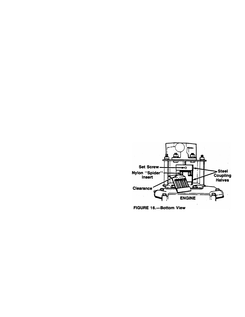
FLEXIBLE PUMP COUPLER
The
flexible
pump
coupler
is
a
nylon
“spider”
insert,
located
between
the
pump
and
engine
shaft.
The
align
ment is very critical. Over a period of time, the coupler
will
harden
and
deteriorate.
For
a
replacement
flexible
pump coupler, order part number 717-0891.
IMPORTANT;
Never
hit
the
pump
shaft
in
any
man
ner,
as
any
blow
will
cause
permanent
damage
to
the pump.
When
replacing
the
flexible
pump
coupling,
proceed
as follows.
1.
Place the coupling half onto the engine shaft. Make
certain
there
is
clearance
between
the
coupling
half and the engine. Tighten the set screw.
2.
Mount the pump onto the coupling support bracket.
Tighten securely.
3.
Carefully slide coupling half onto pump shaft (make
certain set screw is loose). Slide the key into place
on the shaft.
4.
Install
the
nylon
“spider”
insert
into
coupling
half
on the engine shaft.
5.
Place
the
coupling
shield
in
position
on
the
hex
bolts.
Rotate
the
keyway
on
the
pump
shaft
so
it
is toward the bottom.
6.
Attach
the
coupling
support
bracket
to
the
hex
bolts,
carefully
sliding
the
coupling
half
over
the
“spider”
insert.
Secure
coupling
shield
and
coup
ling
support
bracket
with
lock
washers
and
hex
nuts. Tighten securely.
7.
Adjust
the
two
coupling
halves
(steel)
so
there
is
between
.010"
and
.060"
clearance
between
the
two
halves
(at
least
the
thickness
of
a
matchbook
cover,
up
to
1/16"
maximum).
See
figure
16.
Tighten
the
set
screw
in
the
coupling
half
on
the
pump shaft.
NOTE:
Make certain proper clearance is obtained
before tightening set screw.
PUMP
TIRE PRESSURE
Check
sidewall
of
tire
for
manufacturer’s
recommended
maximum
tire
pressure.
If
this
information
does
not
ap
pear on your tire, maximum tire pressure under any cir
cumstances
is
30
p.s.i.
Equal
pressure
should
be
maintained on both tires.
INSTALLATION OF TIRE TO RIM
A
WARNING:
The
following
procedure
must
be
followed
when
removing
Or
installing
a
tire to the rim.
1. Be certain rim is clean and free of rust.
2.
Lubricate both the tire and rim generously.
11