Operation – MTD 24677A User Manual
Page 8
Attention! The text in this document has been recognized automatically. To view the original document, you can use the "Original mode".
L.lFV-iri.r >.\ASH[ K
HAND KNOB
. .
I
\
DIRECTIONAL
DISCHARGE
ASSEMBLY (R)
7. Place the directional discharge assembly (R) over
chute opening. Secure with two hand knobs and
belleville washers. See figure 13.
FIGURE 13.
OPERATION
PRE-START PREPARATIONS
Service engine with gas and oil. See engine manual
packed with vacuum for complete instructions for
care and maintenance of engine. READ DIREC
TIONS CAREFULLY.
TO START ENGINE
After the engine has been properly fueled and oiled
(refer to engine operating and maintenance instruc
tions), start engine following the instructions below.
1.
Move throttle control lever on engine to START
position.
2.
Crank engine. Pull recoil with quick firm pull.
Do not pull out so far the rope stops with a jerk
as this will cause rope failure. Do not allow rope
and handle to snap back into place.
3.
After two or three full firm pulls on recoil (or as
soon as engine fires), move speed control to run
position.
4.
Self-Propelled Units Only - To engage the drive
mechanism, squeeze the clutch grip against the
upper handle. Release the clutch grip to stop the
forward motion.
TO STOP ENGINE
1.
To stop engine, move throttle control lever to
STOP position.
2. Disconnect spark plug wire and ground to prevent
accidental starting while equipment is unattended.
Operate a new engine at intermediate speeds and light
load for the first few hours as you would a new
automotive engine.
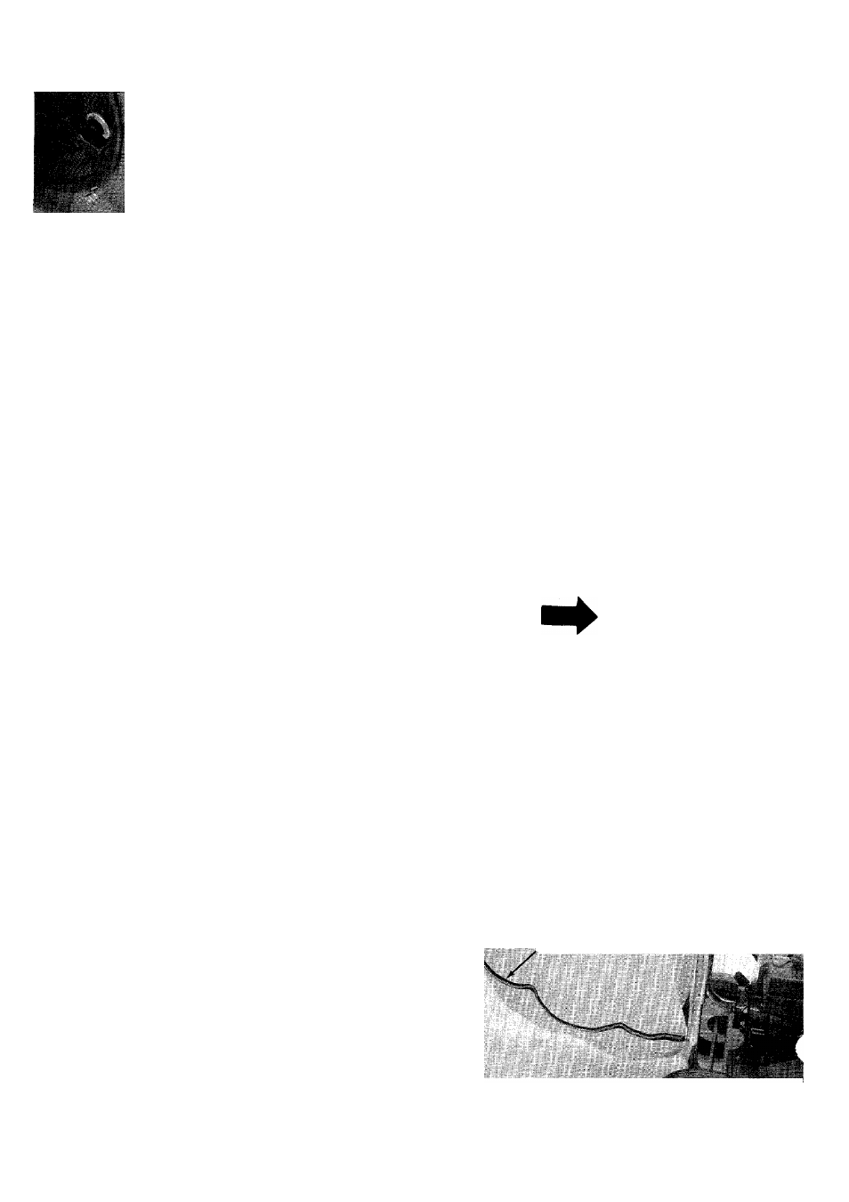
IMPORTANT
The vacuum bag has an air escape
located on the upper right hand side.
The air escape should be opened when
the vacuum is in use. See figure 14.
I
AIR ESCAPE OPENED
LARGE ZIPPER CLOSED
FIGURE 14.