Assembly, Instructions, Assembly instructions – MTD 24677A User Manual
Page 4
Attention! The text in this document has been recognized automatically. To view the original document, you can use the "Original mode".
ASSEMBLY
INSTRUCTIONS
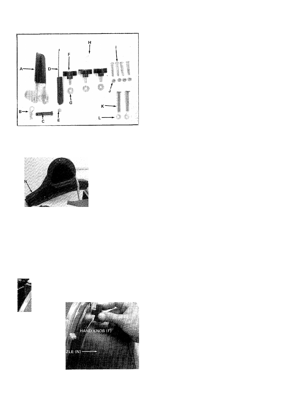
CONTENTS OF HARDWARE PACK
(See Figure 1.)
FIGURE 1.
A
(1)
Clutch Grip Assembly*
B
(1)
Hair Pin Cotter*
C
(1)
Clevis Pin*
D
(1)
Extension Spring*
E
(1)
Lock Nut 1 /4-20 Thread*
F
(3)
Hand Knobs
G
(3)
Belleville Washers
H
(1)
Heavy Flat Washer
1
(4)
Hex Bolts 1/4-20X 1.75" Long
J
(4)
Hex Lock Nuts 1/4-20 Thread
K
(2)
Stud Pins
L
(2)
Push-on Speed Nuts
IVI
LOOSE PARTS IN CARTON
(See Figure 2.)
M
(1)
Bag
N
(1)
Nozzle
0
(1)
Upper Handle
P
(1)
Air Duct Assembly
Q
(1)
Clutch Rod*
R
(1)
Directional Discharge Assembly
S
(1)
Impeller Guard
* Self-Propelled Models 685 and 24687 Oi
FIGURE 2.
m '
otL LEVILLE WASHER (G)
1
TOOLS REQUIRED:
(2) 7/16" Open End or Box Wrenches.
(1) Hammer or Mallet.
(1) Adjustable Wrench.
1.
Place nozzle (N) in position on front of housing
so that it rests in flanges. Secure with one hand
knob (F) and belleville washer (G). See figure 3.
FIGURE 3.