To adjust brake (see fig. 22), Service and adjustments, M>:m – Poulan 168301 User Manual
Page 17
Attention! The text in this document has been recognized automatically. To view the original document, you can use the "Original mode".
SERVICE AND ADJUSTMENTS
i Figs. 19 and 20)
'bf (
I
i['t
'L ' 7ML ii I I
TH FRONT LINKS
LEVEL SIDE-TO-
“ F X b T i r / ‘ I A L l i I ’ l . ' t F r - . ,
1 A H l i ! ' < K M b . 1 b F I t < b '
liT b,
i ' rbf'r'i T'" :
¡‘i i E --
f-r. / hf Li'i.t
t I b
F O i l M l . )
. V I L I
' ^ < ^ 1
SlUh.
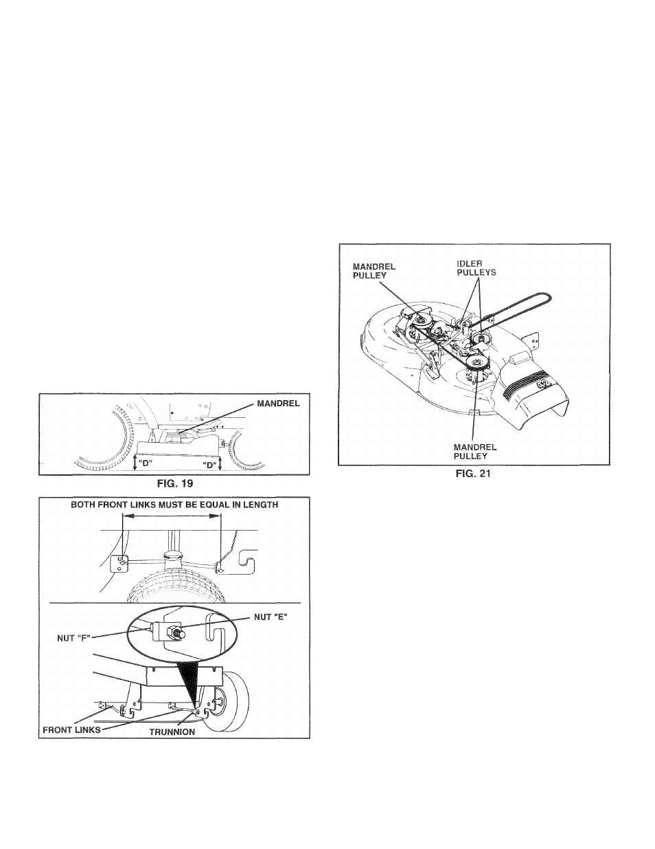
To obtain the best cutting results, the mower housing
should be adjusted so that the front is approximately 1
/
8
"
to
1/2" lower than the rear when the mower
is
in its highest
position.
Check adjustment on right side of tractor. Measure dis
tance “D” directly in front and behind the mandrel at bottom
edge of mower housing as shown.
•
Before making any necessary adjustments, check that
both front links are equal in length. Both links should
be approximately 10-3/8".
•
If links are not equal in length, adjust one link to same
length as other link.
•
To lower front of mower loosen nut “E” on both front
links an equal number of turns.
•
When distance “D” is 1/8" to 1/2" lower at front than
rear, tighten nuts “F” against trunnion on both front
links.
•
To raise front of mower, loosen nut “F” from trunnion on
both front links. Tighten nut “E” on both front links an
equal number of turns.
•
When distance “D" is 1/8" to 1/2" lower at front than
rear, tighten nut “F” against trunnion on both front links.
•
Recheck side-to-side adjustment.
TO ::
fpt
ace
Mowrr
m>:m
belt
fig 1)
If r '(1 V-1 bi,
f - F t-i niavoei'F' > ri «ithout tools.
>ti -in f
vm
i unace L j -ig.
f irking brake.
BELT REMOVAL -
Rtri.vf p-f-vi ‘rnoi rr
j I' ' REMOVE M' ’ "'FM I 1,1 c ' M i! ..r , ' V/ rr i f I . fi Lv in m iii'i I ( . 1 tiCj j I i O .uler pulleys. • Pull belt aw?/trc;m mov.iri BELT INSTALLATION - • Install new belt in reverse order of removal. • Make sure belt is in all pulley grooves and inside all belt guides. • Install mower in reverse order of removal instructions. TO ADJUST BRAKE (See Fig. 22) Your tractor is equipped with an adjustable brake system If tractor requires more than six (6) feet stopping distance at high speed in highest gear, then brake must be adjusted. • Depress clutch/brake pedal and engage parking brake. • Measure distance between brake operating arm and nut “A” on brake rod. • If distance isotherthan 1-1/2", loosen jam nut and turn nut “A” until distance becomes 1-1/2". Retighten jam • Road test tractorfor proper stopping distance as stated above. Readjust if necessary. If stopping distance is FIG. 20 19
which is mounted on the right side of the transaxle.
nut against nut “A”.
still greater than six (6) feet in highest gear, further
maintenance is necessary. Contact your nearest au
thorized service center/department.