Tractor, To remove mower (see fig. 16), To install mower (see fig. 16) – Poulan 168301 User Manual
Page 16: To level mower housing, Service and adjustments
Attention! The text in this document has been recognized automatically. To view the original document, you can use the "Original mode".
SERVICE AND ADJUSTMENTS
A
CAUTION: BEFORE PERFORMING ANY SERVICE OR ADJUSTMENTS:
Depress clutch/brate pedal lully ar^d set
Place gearshift lever In neutral fN| position
Place attachment clyich iri ‘ DISENGAGED t«
Turn ignition key “OFF’ and remove key.
Make sure the blades and all moving parts have completely stopped.
Disconnect spark plug wire from spark piug and place wire where it cannot come in contact with
plug.
TRACTOR
TO REMOVE MOWER (See Fig. 16)
Mower will be easier to remove from the right side of tractor.
•
Place attachment clutch in “DISENGAGED” position.
•
Move attachment lift leverforward to lower mowerto its
lowest position.
Roil belt off engine pulley.
Disconnect clutch rod from clutch lever by removing
retainer spring.
Disconnect anti-sway bar from chassis bracket by
removing retainer spring.
Disconnect suspension arms from rear deck brackets
by removing retainer springs.
Disconnect front links from deck by removing retainer
springs. .
Raise lift lever to raise suspension arms. Slide mower
out from under tractor.
IMPORTANT: IF AN ATTACHMENT OTHER THAN THE
MOWER DECK IS TO BE MOUNTED ON THE TRACTOR,
REMOVE THE FRONT LINKS.
TO INSTALL MOWER (See Fig. 16)
•
Raise attachment lift lever to its highest position.
•
Slide mower undertractorwith discharge guard to right
side of tractor.
•
Lower lift lever to its lowest position.
•
Install mower in reverse order of removal instructions.
CLUTCH ROD
SUSPENSION
ARMS
CLUTCH LEVER
RETAINER
SPRING
ENGINE
PULLEY
FRONT
LINK
RETAINER
SPRINGS
(BOTH SIDES)
RETAINER
SPRING
ANTI-SWAY BAR
RETAINER
SPRINGS
(BOTH SIDES)
FIG. 16
TO LEVEL MOWER HOUSING
Adjust the mowerwhile tractor is parked on level ground or
driveway. Make sure tires are properly inflated (See
“PRODUCT SPECIFICATIONS” on page 3 of this manual).
If tires are over or underinflated, you will not properly adjust
your mower.
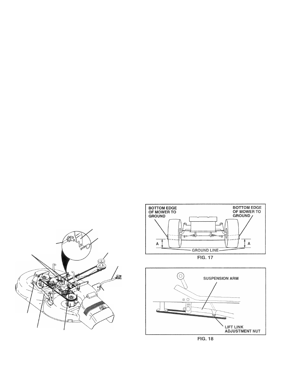
SIDE-TO-SIDE ADJUSTMENT (See Figs. 17 and 18)
•
Raise mower to its highest position.
•
At the midpoint of both sides of mower, measure height
from bottom edge of mowerto ground. Distance “A” on
both sides of mower should be the same or within 1 /4"
of each other.
•
If adjustment is necessary, make adjustment on one
side of mower only.
•
To raise one side of mower, tighten lift link adjustment
nut on that side.
•
To lower one side of mower, loosen lift link adjustment
nut on that side.
NOTE: Three full turns of adjustment nut will change
mower height about 1/8".
•
Recheck measurements after adjusting.
18