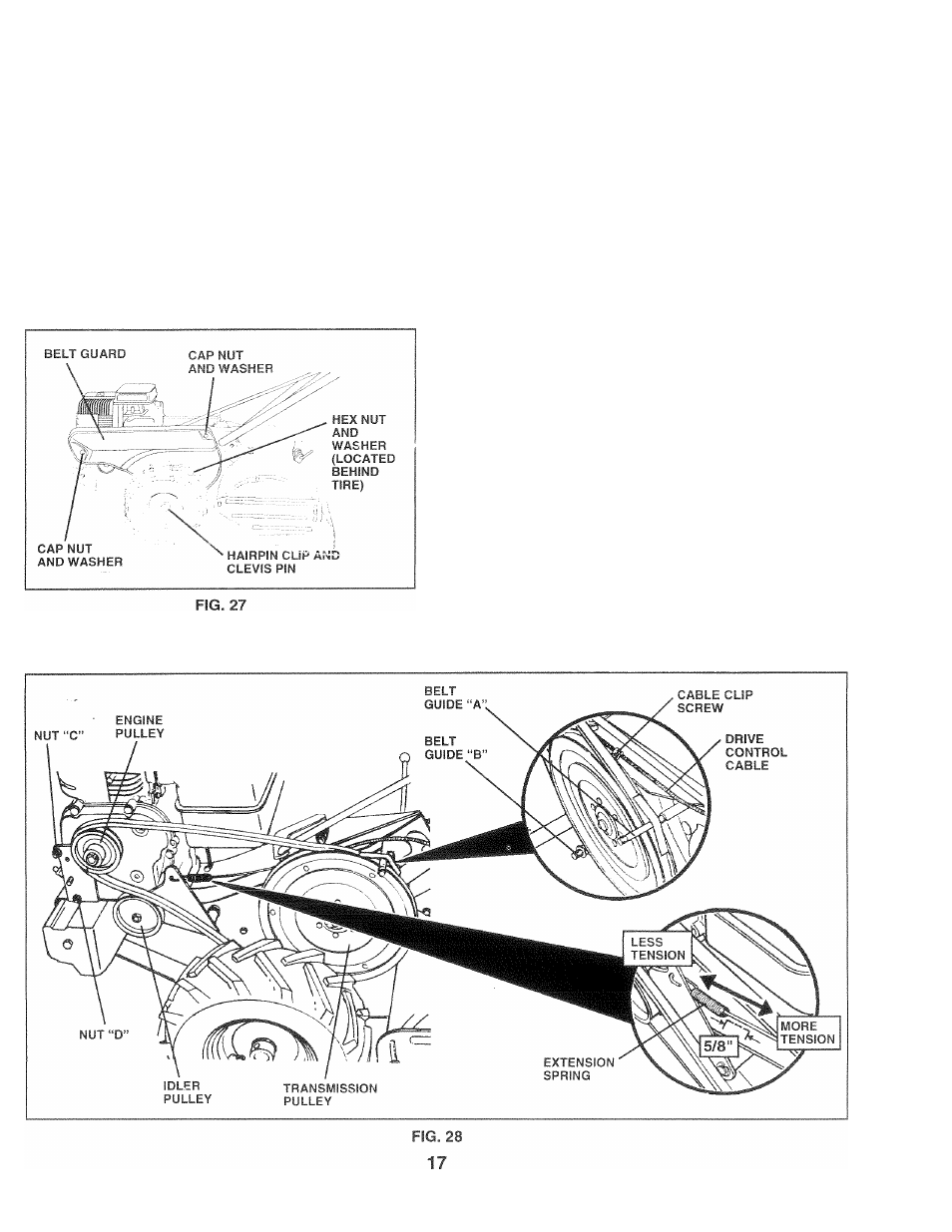
Tfi mmnm bf;lt guard (see fig. 27), To replace ground drive belt (see figs. 27 and 28), Service and adjustments – Poulan CHDR500B User Manual
Page 17: Mmnm, Ground drive belt adjustment (see fig. 25)
Attention! The text in this document has been recognized automatically. To view the original document, you can use the "Original mode".
SERVICE AND ADJUSTMENTS
Tfi
mmnm
BF;LT
guard
(See Fig. 27)
N<.
1 1
^; i '-»i -aseof removal, remove hairpin clip and clevis
pin fif'ii ii-)t wheel. Pull wheel out from tiller about 1 inch
< m ) .
« 0
(2) cap nuts and washers from side of belt
gun 0
•
Remove hex nut and washer from bottom of belt guard
(located behind wheel).
•
Pull belt guard out and away from unit.
•
Replace belt guard by reversing above procedure.
TO REPLACE GROUND DRIVE BELT (See
Figs. 27 and 28)
•
Move left wheel and remove belt guard as described in
“TO REMOVE BELT GUARD”.
•
Loosen belt auides “A” and “B” and also nuts “C” and
“D”.
•
Remove old belt by slipping from engine pulley first.
® Place nev^ belt in groove of transmission pulley and
into engine pulley. BELT MUST BE IN GROOVE ON
TOP OF IDLER PULLEY. NOTE POSITION OF BELT
TO GUIDES.
•
Tighten belt guides “A” and “B” and nuts “C” and' “D”.
» Check belt adjustment as described below.
•
Replace belt guard.
•
Reposition wheel and replace clevis pin and hafrpin
clip.
GROUND DRIVE BELT ADJUSTMENT (See
Fig. 25)
For proper belt tension, the extension spring should have
about 5/8 inch (16 mm) stretch when drive control bar is in
“ENGAGED” position. This tension can be attained as
follows:
•
Loosen cable clip screw securing the drive control
cable.
•
Slide cable forward for less tension and rearward for
more tension until about 5/8 inch (16 mm) stretch is
obtained while the drive control bar is engaged.
•
Tighten cable clip screw securely.