Ahaching the hoses, Ahaching the fenders, Final assembly – MTD 638 User Manual
Page 8
Attention! The text in this document has been recognized automatically. To view the original document, you can use the "Original mode".
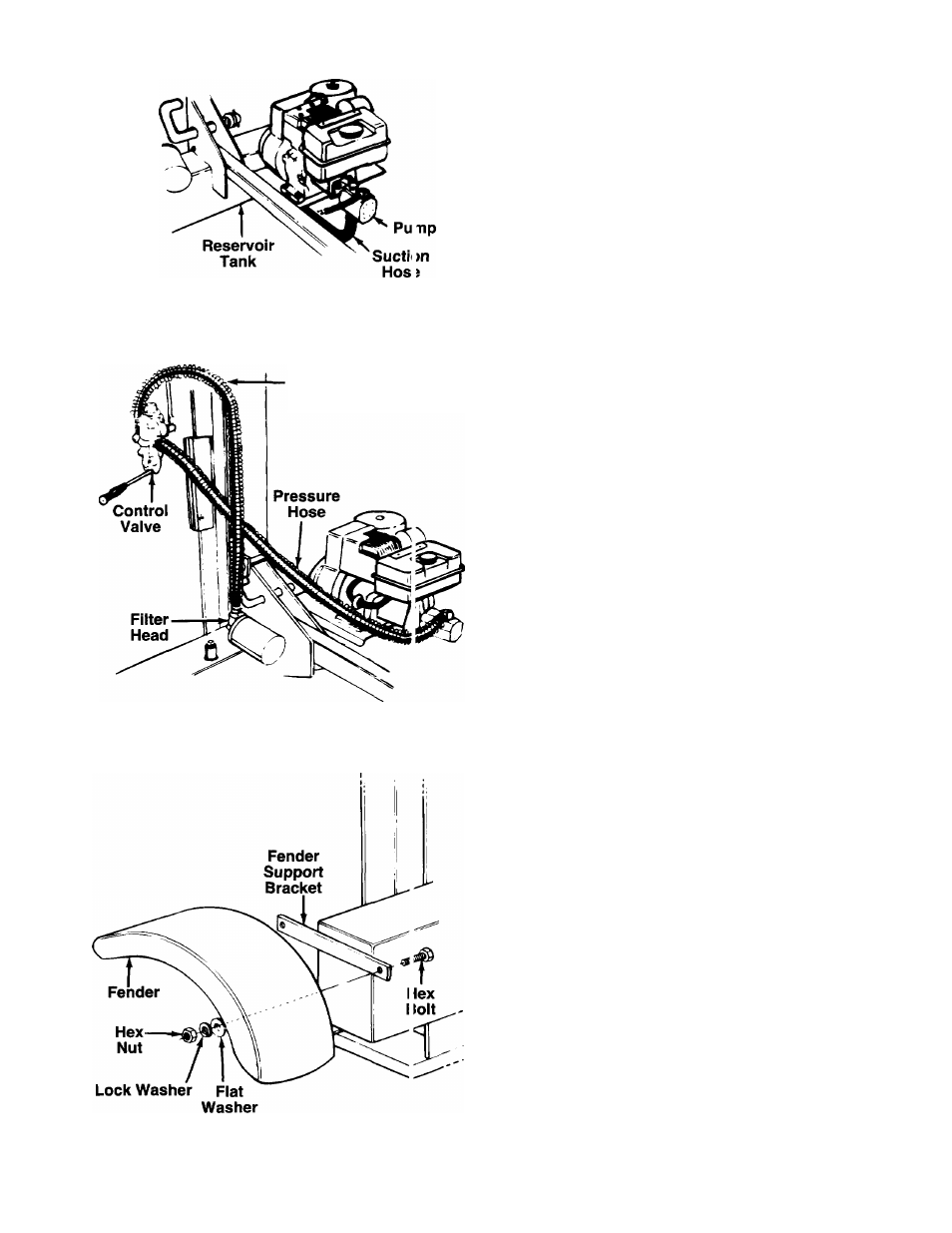
FIGURE 9.
AHACHING THE HOSES
Suction Hose
1. The suction hose is attached to the reservoir
tank, beneath the engine mounting bracket. See
-------figure 9. Loosen the hose clamp on the free end
of the hose using a screwdriver.
2. Remove the protective cap from the fitting on the
bottom of the pump (some oil may flow from
pump). Attach the end of the suction hose to the
fitting on the bottom of the pump. Place the hose
clamp at the base of the fitting, and tighten
securely.
Return
Hose
FIGURE 10.
NOTE:
The return and pressure hoses are protected
by a wire hose guard. It may be necessary to push
hose guards back to install hoses to the log splitter.
Return Hose
1. The return hose is attached to the top of the control
valve. Loosen the hose clamp on the free end of the
hose using a screwdriver. Cut off the securing strap.
2. Remove the protective cap from the fitting on top
of the filter head. Attach the end of the hose to
------the fitting on top of the filter head. See figure 10.
Place the hose clamp at the base of the fitting,
and tighten securely.
Pressure Hose
The pressure hose is attached to the top of the pump.
Route the hose as shown in figure 10. Secure the
pressure hose to the bottom of the control valve,
using two wrenches.
AHACHING THE FENDERS
1. Using two 1/2" wrenches, remove the hex nuts,
lock washers, flat washers and hex bolts from the
fender support brackets.
Place the fenders in position against the fender
support brackets. Insert hex bolts through holes
in support brackets and fenders. Secure with flat
washers, lock washers and hex nuts. See figure
-11. Tighten securely.
2
.
FIGURE 11.
FINAL ASSEMBLY
1. Pull the locking rod on the beam support/latch
bracket away from the log splitter tongue (refer to
figure 7), and pivot it down. Carefully lower the
wedge, beam and cylinder assembly to the horizon
tal position. Secure the beam with the locking rod.
2. Make certain all nuts, bolts and hose clamps are
tightened securely.
3. Before operating the log splitter, make certain
to follow “Initial Preparation” instructions in
Operation section.