How your log splitter operates, The pump, The directional valve and cylinder – MTD 638 User Manual
Page 14: Operational problems
Attention! The text in this document has been recognized automatically. To view the original document, you can use the "Original mode".
HOW YOUR
LOG
SPLITTER OPERATES
Cylinder
Cylinder
Pilot
Pressure
Line
Pump
Reservoi'
High Volume
Low Pressure
Gear Section
Low Volume
High Pressure
Gear Section
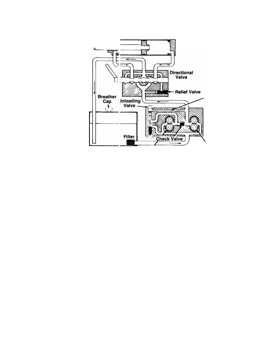
THE PUMP
A two-stage log splitter pump has one large and one
small gear section, using common inlet ard outlet
ports. Below a preset pressure (called unloading pres
sure) a check valve between the two gear sections
allows both flows to combine. Together, the iwo gear
sections create a large volume flow which produces
rapid cylinder movement under low load cond tions.
Above unloading pressure, a pilot press jre line
(which simulates actual pressure at the cylinc er) acti
vates the unloading valve, which causes thr flow to
bypass the large gear section and return to the pump
inlet area. The small gear section is now o Derating
alone, and will generate the higher pressure neces
sary for the actual log splitting operation.
The original factory setting for the unloading valve is
designed to provide maximum flow while
rt
maining
below engine stalling load. Note: Splitting ci ipability
is not affected by the setting of the unloading
valve. Do not attempt to adjust or reset it without
a pressure gauge (should be performe d by an
authorized service deaier oniy).
THE DIRECTIONAL VALVE AND CYLINDER
From the pump, oil flows to a four way, three position
directional valve. At the neutral position tf is valve
directs the flow back to the oil reservoir, bypassing
the cylinder. When the directional valve is directing
the flow to the back of the cylinder, the cyli ider rod
extends quickly until it meets significant resistance.
Upon reaching unloading pressure, movemeit of the
shaft will slow but will continue forward. If the pres
sure reaches a preset maximum (called relief valve
pressure) the relief valve, located within the direction
al valve, will allow the flow to bypass the cylinder and
return to the reservoir. This can happen when the
cylinder rod meets excessive resistance, or when it
reaches the end of its stroke and can move no farther.
NOTE: Never operate at relief valve pressure for
more than a few seconds.
When the directional valve is directing the flow to the
front of the cylinder, the rod will retract quickly since it
is encountering no resistance. The relief valve will
momentarily bypass the flow at the end of the return
stroke but the directional valve should then automati
cally return to the neutral position, directing the flow
directly into the reservoir. This serves to protect the
pump from possible damage due to prolonged opera
tion at relief valve pressure.
Because of the potential for system damage, the relief
valve is carefully and precisely preset by the manu
facturer.
NOTE: The user should not attempt to adjust or
change the setting of the relief valve.
OPERATIONAL PROBLEMS
If you have trouble with your log splitter, please refer
to the Hydraulic Trouble Shooting Guide.
NOTE: Readjustment of valves or disassembly of
pump should be performed by an authorized ser
vice dealer only.
14