To operate log spliher, To transport log spliher, Adjustments – MTD 638 User Manual
Page 11: Splining wedge
Attention! The text in this document has been recognized automatically. To view the original document, you can use the "Original mode".
TO OPERATE LOG SPLIHER:
1. Set throttle at maximum speed.
2. Place the log upright, on top of end plate for verti
cal operation, and on top of beam for horizontal
operation.
3. Push the control handle in forward position until
the splitting wedge just contacts the log. Release
the control handle.
4.
5.
Step behind the reservoir tank (see figures 13 or
14) and push the control handle in forward posi
tion until the log is split.
Move the control handle to reverse position to
return the splitting wedge.
A
WARNING: If the fluid becomes exces
sively hot at any time during operation,
stop the unit and allow the fluid to cool
down. Maximum performance wili not be
obtained from your log splitter if the fluid
is too hot. Use extreme caution as con
tacting hot fluid could result in serious
personal injury.
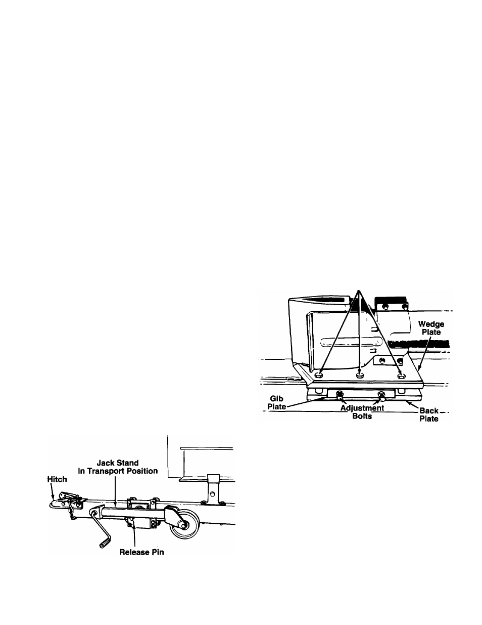
TO TRANSPORT LOG SPLIHER
1. Unlock the beam from the vertical position by
pulling out on the locking rod and pivoting it to the
right.
2. Lower the beam to its horizontal position. Make
certain the beam is latched securely with the ver
tical position release rod.
3. Raise or lower jack stand to attach the hitch to a
towing vehicle. Make certain to latch securely.
Attach the safety chains to the towing vehicle.
4. Raise the jack stand wheel to its highest position.
Pull out on release pin and pivot the jack stand
until it locks in the horizontal position. See figure
16
.
ADJUSTMENTS
A
WARNING: Always stop the engine and
disconnect the spark plug wire before
performing any adjustments.
2
.
SPLiniNG WEDGE
As normal wear occurs, periodically adjust the bolts
on the side of the wedge plate as follows to eliminate
the excess space between the wedge plate and the
beam. See figure 17.
1. Loosen the three hex bolts on top of the wedge
plate (beneath the splitting wedge).
Loosen the lock nuts on the two adjustment bolts
on the side of the gib plate, located beneath the
splitting wedge. Turn the adjustment bolts in until
snug, then back them off slowly until the wedge
assembly will slide on the beam.
Tighten the lock nuts securely against the gib
plate to hold the adjustment bolts in this position.
Retighten the three hex bolts on top of the wedge
plate.
3.
4.
Hex Bolts
FIGURE 16.
FIGURE 17.
Periodically remove and replace the “gibs” (spacers)
between the wedge plate and the back plate as fol
lows.
NOTE: If desired, the gibs may be rotated and/or
turned over for even wear.
1. Remove the center bolt on top of the wedge
plate. Slide the gib plate out. See figure 17.
2. Remove and replace the gibs. Reassemble the
gib plate, making certain flat washers are in place
under the gib plate.
3. Readjust the bolts on the side of the wedge plate
as instructed above.
11