Assembly instructions, Unpacking, Installation of wheels – MTD 638 User Manual
Page 5
Attention! The text in this document has been recognized automatically. To view the original document, you can use the "Original mode".
ASSEMBLY INSTRUCTIONS
Tools Required for Assembly
(1) Soft Hammer or Mallet
(2) 9/16" Wrenches*
(2) 1/2" Wrenches*
(1) 7/16" Wrench*
(1) Adjustable Wrench
(1) Screwdriver
(1) Pliers
(1) Knife
(1) Cutters
*Adjustable Wrenches may be used.
Other Materials Required for Assembly:
Engine Oil
Unleaded Gasoline
Approximateiy 7.6 Gallons of Dexron II Automatic
Transmission Fluid or 10W Non-Foaming Hydraulic
Fluid
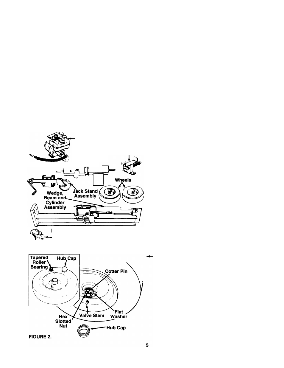
Engine and
Pump Assembly
Reservoir
Tank Assembly
i
Beam Support/
Latch Bracket
-Hitch
Y Assembly
FIGURE 1.
Tongue Assembly
IMPORTANT: This unit has been shipped without
gasoline or oil in the engine. Be certain to service
engine with gasoiine and oii before operating your
iog splitter. Refer to the separate engine manual.
UNPACKING
A
WARNING: Exercise extreme caution as
parts are very heavy. Mechanical han
dling equipment should be used, or suffi
cient peopie to prevent injury.
Remove the log splitter parts from the carton by cut
ting the corners of the carton. Unbolt parts bolted to
bottom of carton. Make certain all parts and literature
have been removed from the carton before the carton
is discarded. Most of the hardware for assembly of
the log splitter has been placed in position on the vari
ous parts.
Parts in Carton (See figure 1)
Reservoir Tank Assembly (Bolted to bottom of
carton)
Engine and Pump Assembly (Bolted to bottom of
carton)—Connected to Wedge, Beam and
Cylinder Assembly by Pressure Hose
Wedge, Beam and Cylinder Assembly
Tongue Assembly
Wheels
Jack Stand Assembly
Fenders (Not Shown)
Small box which contains:
Hitch Assembly
Beam Support/Latch Bracket
Plastic hardware bag (4 bolts, washers, nuts)
Plastic bag containing four roller bearings, two
grease seals and two hub caps
Plastic bag containing grease
INSTALLATION OF WHEELS
Attach the wheels to the reservoir tank assembly as
follows. See figure 2.
1. Block up the reservoir tank assembly about 8
inches.
2. Remove the roller bearings, grease seals and
hub caps from the plastic bag.
3. Pack the tapered roller bearings with wheel bear
ing grease. Work grease between the rollers.
Insert a bearing (smaller end first) into the inside
hub of each wheel (valve stem is on the outside of
the wheel). Insert a grease seal with open side fac
ing inward into the inside hub of each wheel. Tap
on using a soft hammer or mallet. Outside surface
of seal should be even with the end of the hub.
NOTE:
A large socket can be placed against the
grease seal to aid in properly seating the seal.
4. Remove the cotter pin, hex slotted nut and flat
washer from each axle. Place one wheel on each
axle, hub side toward the log splitter (valve stem
facing outward).