Important, Note, Tire pressure – MTD 219-406-000 User Manual
Page 9: Controls -—location and use, Throttle control, Forward drive ciutch lever, Reverse drive clutch lever, Controls
Attention! The text in this document has been recognized automatically. To view the original document, you can use the "Original mode".
2. Check the adjustment of the drive clutch controls
with the engine running.
IMPORTANT
Service engine with oil and gasoline
before starting the engine. Refer to the
separate engine manual packed with ,
your tiller.
Place the unit against a solid object (wall, fence,
etc.). With the forward drive clutch lever and tine
clutch lever released and the reverse drive clutch
lever in the neutral position, carefully start the
engine.
Ac
WARNING
i
»♦♦♦♦♦♦♦
BE PREPARED TO STOP ENGINE
IMMEDIATELY, as tiller may go in
reverse motion.
NOTE
The unit moves faster in reverse than
in forward.
Note which (if any) of the following conditions exist in
your unit. Adjust the cable(s) at the cable brackets by
following the appropriate instructions.
Ac
WARNING
♦♦♦♦♦♦♦«
Stop the engine before making any
cable adjustments.
A.
TILLER HAS FORWARD MOTION with forward
drive clutch lever released. Adjust the forward cable
(right hand handle) by loosening the hex nut on top
of the cable bracket three or four turns, then tighten
ing the hex nut beneath the cable bracket.
B. TILLER HAS REVERSE MOTION with reverse drive
clutch lever in neutral. Adjust the reverse cable
(beneath the handle panel) by loosening the nut
beneath the cable bracket three or four turns, then
tightening the hex nut on top of the cable bracket.
C. TILLER DOES NOT HAVE FORWARD MOTION
with forward drive clutch lever in forward. Adjust the
forward cable by loosening the hex nut beneath the
cable bracket three or four turns, then tightening the
hex nut on top of the cable bracket.
D.
TILLER DOES NOT HAVE REVERSE MOTION
with the reverse drive clutch lever in reverse. Ad
just the reverse cable by loosening the hex nut on
top of the cable bracket three or four turns, then
tightening the hex nut beneath the cable bracket.
TIRE PRESSURE
The tires on your unit may be over-inflated for shipp
ing purposes. Reduce the tire pressure before
operating the unit. Recommended operating tire
pressure is approximately
12
p.s.i. (check sidewall of
tire for tire manufacturer’s recommended pressure).
Ac
WARNING
j
Maximum
tire
pressure
under
any
circumstances is 30 p.s.i. Equal tire
pressure should be maintained on both
tires.
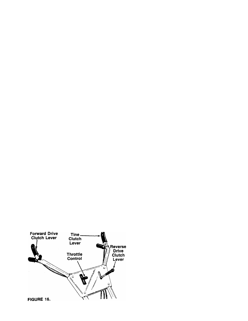
CONTROLS
-—Location and Use
Throttle Control
The throttle control lever is located on the right hand
side of handle panel and controls the engine speed.
See figure 16.
1. Start—Push throttle control lever forward (down)
to start position.
2. Stop—Pull lever back (upward) to stop the engine.
Tine Clutch Lever
The tine clutch lever is located on the left handle. See
figure 16. Squeeze the lever against the handle to
engage the tines. Release the lever to stop the tines
from turning.
Forward Drive Ciutch Lever
The forward drive clutch lever is located on the left han
dle. See figure 16. Squeezing the lever against the han
dle engages the forward wheel drive. Release the lever
to stop the forward motion.
Reverse Drive Clutch Lever
The reverse drive clutch lever is located on the left hand
side of handle panel. See figure 16.
The reverse drive clutch lever may be placed in one
of two positions.