Note, Assembly, Contents of hardware pack; (see figure 1) – MTD 219-406-000 User Manual
Page 4: Depth stake installation, Assembiy
Attention! The text in this document has been recognized automatically. To view the original document, you can use the "Original mode".
NOTE
Left and right is determined from the
operator’s position, standing behind the
tiiier.
B-
ASSEMBLY
NOTE
This unit is shipped WITHOUT GAS
OLINE or OIL. After assembly, see
separate engine manuai for proper
fuei and engine oil recommendations.
-Contents of Hardware Pack; (See Figure 1)
FIGURE 1.
AE
A
B
C
D
E
F
G
H
I
L
M
N
O
P
Q
R
S
T
u
V
w
X
(
1
)
(
1
)
(
1
)
(1)
(
1
)
(4)
(4)
(4)
(4)
(
2
)
(4)
(4)
(4)
(4)
(4)
(
1
)
(
1
)
(
1
)
(
1
)
(
1
)
(
1
)
(
1
)
Long
/
Hex Bolt 3/8-16 X 3/4" Long
Flat Washer 3/8" I.D.
Ball Knob
Clevis Pin
Hairpin Cotter
Hex Bolts 3/8-16
X
1.0" Long
Belleville Washers 3/8" I.D.
Lock Washers 3/8" I.D.
Hex Nuts 3/8-16 Thread
Cable Ties
Carriage Bolts 5/16-18 x 1.75"
Lock Washers 5/16" I.D.
Hex Nuts 5/16-18 Thread
Belleville Washers 5/16" I.D.
Hex Nuts 5/16-18 Thread
Hex Bolt 1/4-28 X 1" Long
Hex Lock Nut V4-28 Thread
Rubber Washer
Flat Washer 5/16" I.D. x 7/8" O.D.
Hex Lock Nut 5/16-18 Thread
Reverse Drive Clutch Lever (Not Shown)
Self-Tapping Screw
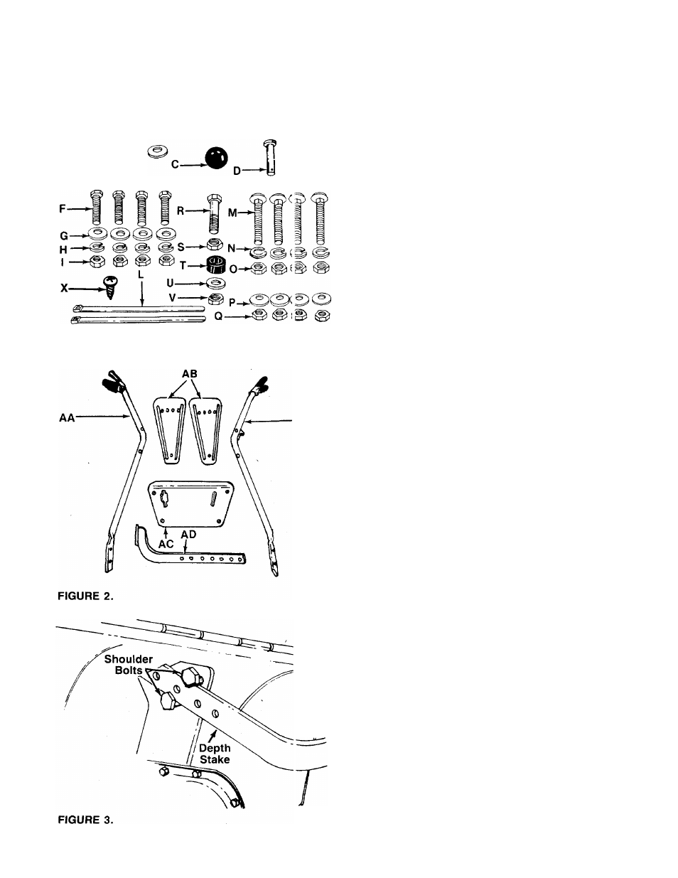
-Loose Parts in Carton: (See figure 2)
AA (1) Handle—R.H.
AB (2) Side Shields
AC (1) Handle Panel
AD (1) Depth Stake Assembly
AE (1) Handle—LH.
1. Remove tiller, loose parts and hardware pack from
carton. Make certain all parts and literature have
been removed from the carton before the carton
is discarded.
2. Extend the control cables attached to the tiller and
place on the floor. Be careful not to bend or kink
the cables.
DEPTH STAKE INSTALLATION
1.
Raise the tine shield hinge flap assembly. Insert
the depth stake assembly (AD) between the two
shoulder bolts and up through the tine shield
------- assembly as shown in figure 3.
NOTE
For clarity, figure 3 was taken with tiller
raised on end. It is not necessary to
raise the tiller.