1 fuel primer, 2 start/stop switch, 3 fuse – Generac Power Systems 00862-2 User Manual
Page 9: 4 2.1.4 main breaker, 1 remote panel plug-in receptacle, 2 models 4057-0 and 4184-0, Fuel primer, Start/stop switch, Fuse, Main breaker
Attention! The text in this document has been recognized automatically. To view the original document, you can use the "Original mode".
Section 2 - Operation
Series QP55-G Recreational Vehicle Generator
OPERATION
2.1
GENERATOR CONTROL PANEL
The following features are mounted on the genera
tor control panel (Figure 2.1):
Figure 2.1 - Generator Control Panel
FUSE MAIIV
START ISA BREAKER
♦ 2.1.1 FUEL PRIMER
Before starting a cold engine (if it has not been
started in more than two weeks), you must press
this switch for approximately five seconds to bring
fuel from the tank to the carburetor or fuel regula
tor (LP). This rocker type switch springs back into
its original position when you release it.
♦ 2.1.2 START/STOP SWITCH
To crank and start the engine, hold this switch in
the START position. Release the switch when the
engine starts. To stop an operating engine, press
and hold the switch in the STOP position until the
engine shuts off. The switch center position is the
RUN position.
♦ 2.1.3 FUSE
The fuse protects the engine’s DC control circuit
against electrical overload. If the fuse element has
melted open due to overloading, the engine cannot
be cranked. If you must replace the fuse, use only
an identical replacement.
4 2.1.4 MAIN BREAKER
The main breaker protects the generator’s AC out
put
circuit
against
overload
or
exceeding
wattage/amperage capacity.
2.2
OPTIONAL REMOTE
START/STOP PANELS
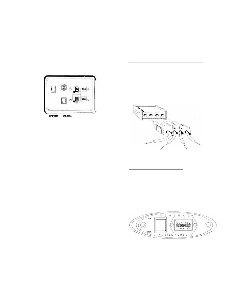
♦ 2.2.1 REMOTE PANEL PLUG-IN RECEPTACLE
A plug-in receptacle (Figure 2.2) is provided on the
generator set, above the muffler enclosure. Use this
receptacle to connect an optional remote-mounted
start/stop panel to the generator. Installation of
such a panel will permit you to start and stop the
generator
engine
from
any
convenient
location
Inside the vehicle.
Figure 2.2
—
Remote Panel Plug-in Receptacle
WIRE #18
(STOP)
WIRE #14
(ENGINE RUN
SIGNAL)
WIRE #0
(GROUND)
WIRE #17
(CRANK)
♦ 2.2.2 MODELS 4057-0 AND 4184-0___________________
These remote panels mount a rocker type switch, a
“Generator Run” lamp and an hourmeter (Figure
2.3). The hourmeter should be used in conjunction
with the maintenance operations found in Part I of
this manual.
Figure 2.3
—
Models 4057-0 and 4184-0
Remote Panel
Generac* Power Systems, Inc.