Assembly instructions – MTD 112-530A User Manual
Page 4
Attention! The text in this document has been recognized automatically. To view the original document, you can use the "Original mode".
0
0
00
0
©
ASSEMBLY INSTRUCTIONS
FIGURE 1.
Lower
Handle
FIGURE 2.
NOTE
This unit is shipped WITHOUT GAS
OLINE or OIL. After assembly, see
operating section of this manual for
proper fuel and engine oil recom
mendations.
Loose Parts in Carton:
(1) Lower Handle
(1) Lower Handle Support—Left Hand
Lower Handle Support—Right Hand
Upper Handle Assembly
Hardware Pack
Control Rod
(
1
)
(
1
)
(
1
)
(
1
)
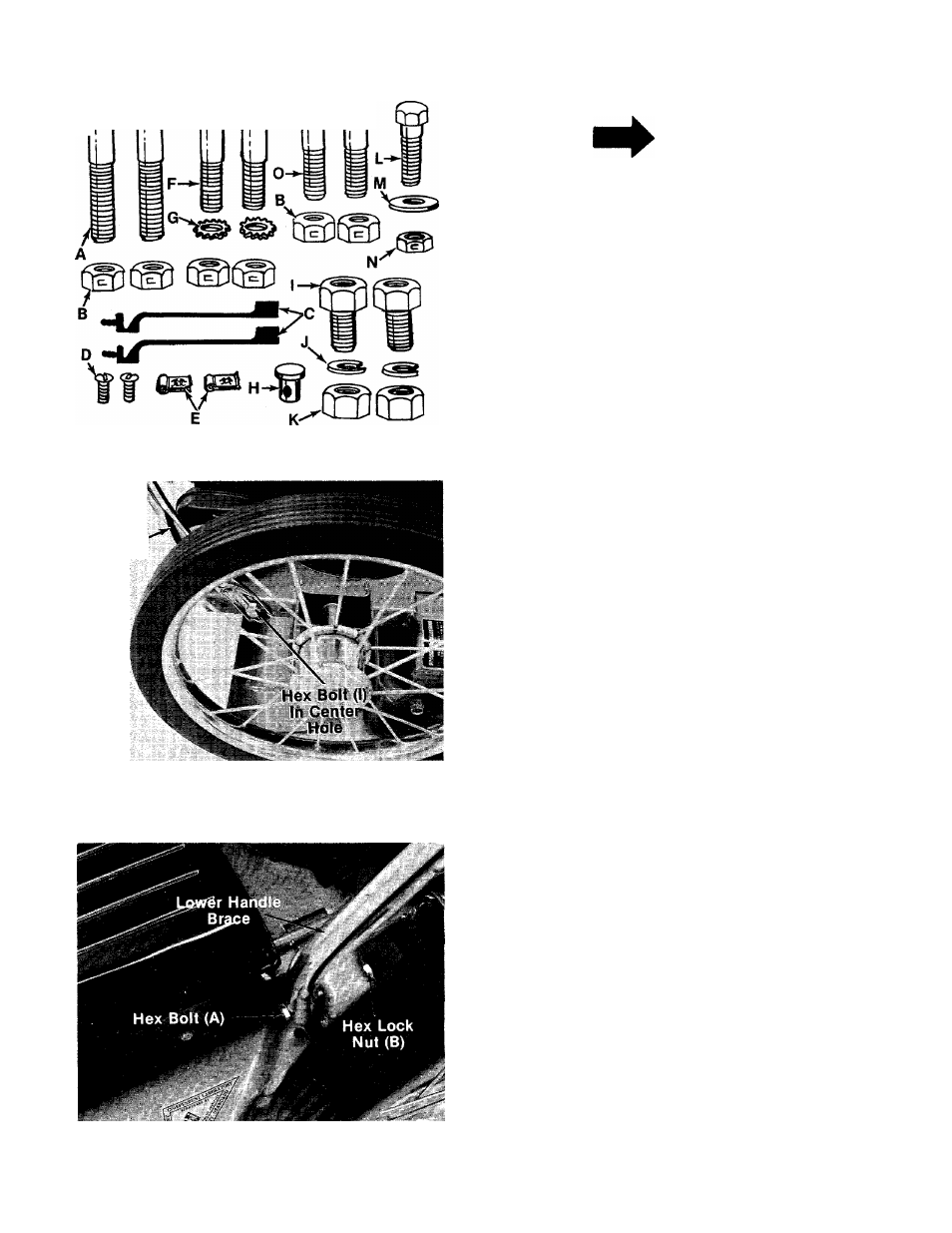
Contents of Hardware Pack: (See Figure 1)
A
B
C
D
E
F
G
H
I
J
K
L
M (1)
N (1)
O (2)
P (1)
Q (2)
(
2
)
(
6
)
(
2
)
(
2
)
(
2
)
(
2
)
(
2
)
(
1
)
(
2
)
(
2
)
(
2
)
(
1
)
Hex Bolts V4-20 x 2.50" Long
Hex Center Lock Nuts V4-20 Thread
Cable Ties
Truss Machine Screws #10-24 x .38" Long
Speed Nuts #10-24
Hex Bolts V4-20 x 1.50" Long
External Lock Washers
Ferrule
Hex Bolts 3/8-16
X
.62" Long
Lock Washers 3/8" I.D.
Hex Nuts 3/8-16 Thread
Hex Bolt
1/4-28 X
.75" Long
Flat Washer .510 I.D. x .750 O.D.
Hex Center Lock Nut V
a
-ZS Thread
Hex Bolt
1/4-20 X
1.25" Long
Lockout Lever Assembly (Not Shown)
Hand Grips (Not Shown)
Remove the lawn mower, loose parts, hardware
pack and literature from the carton. Make certain
all parts and literature have been removed before
the carton is discarded.
Extend throttle control assembly which is at
tached to the rear of the mower and place on the
floor. Be careful not to bend or kink control wire.
HANDLE ASSEMBLY
1. Assemble lower handle to frame assembly by
lining up hole in lower handle with center hole
in frame assembly. See figure 2. Secure using
hex bolts (I), lock washers (J) and hex nuts (K)
on the inside of frame. Two 9/16" wrenches
are required.
2. Fasten bottom of left and right hand lower
------ handle supports to frame using hex bolts (A)
and hex lock nuts (B). See figure 3.
FIGURE 3.