Figure 12, 1/4” of, Thread – MTD 312-980I000 User Manual
Page 7
Attention! The text in this document has been recognized automatically. To view the original document, you can use the "Original mode".
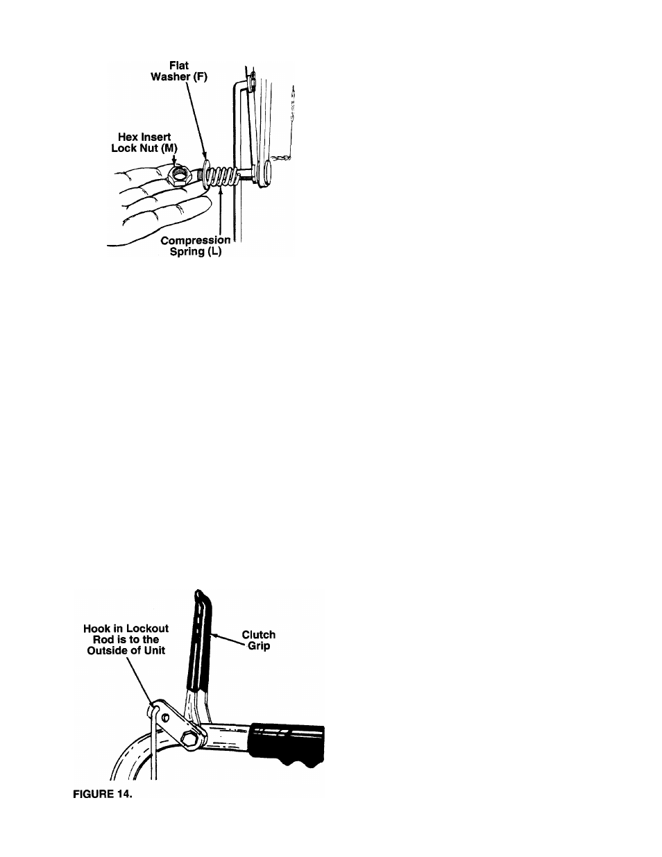
18. Secure with flat washer (F), compression spring
--------(L) and hex insert lock nut (M). See figure 12.
Tighten lock nut until compression spring returns
the shift lever into detent slots on handle panel.
NOTE: The adjustment of the shift rod must be
checked as described in step 23 before the unit is
operated.
FIGURE 12.
Left Hand
Lockout
Rod
1
-
1
/
2
"
Thread
FIGURE 13.
' Right Hand
Lockout
Rod
} 1/4” of Thread
19. There is a left and a right hand lockout rod. The
left hand lockout rod is label “L”.
Approximate
initial settings for the lockout rods
are as follows: The left hand lockout rod for the
drive clutch should have approximately 1-1/2
inches of thread showing below the nut. The right
hand lockout rod for the auger clutch should have
approximately 1/4 inch of thread showing below
------ the nut. See figure 13.
FINAL ADJUSTMENT MUST BE MADE AS
DESCRIBED IN STEPS 21 AND 22.
If the left
hand lockout rod is not adjusted correctly, the
shift lever cannot be shifted past neutral. If the
right hand lockout rod is not adjusted correctly,
the augers will not stop rotating.
20. Hook the right hand lockout rod into the top hole
provided in the right hand clutch grip (auger
-------clutch). See figure 14. Hook the left hand lockout
rod (labeled “L”) into the top hole in the left hand
clutch grip (drive clutch). The hook is to the out
side of the unit.