Leave open, Left i-land lower handle – MTD 312-980I000 User Manual
Page 4
Attention! The text in this document has been recognized automatically. To view the original document, you can use the "Original mode".
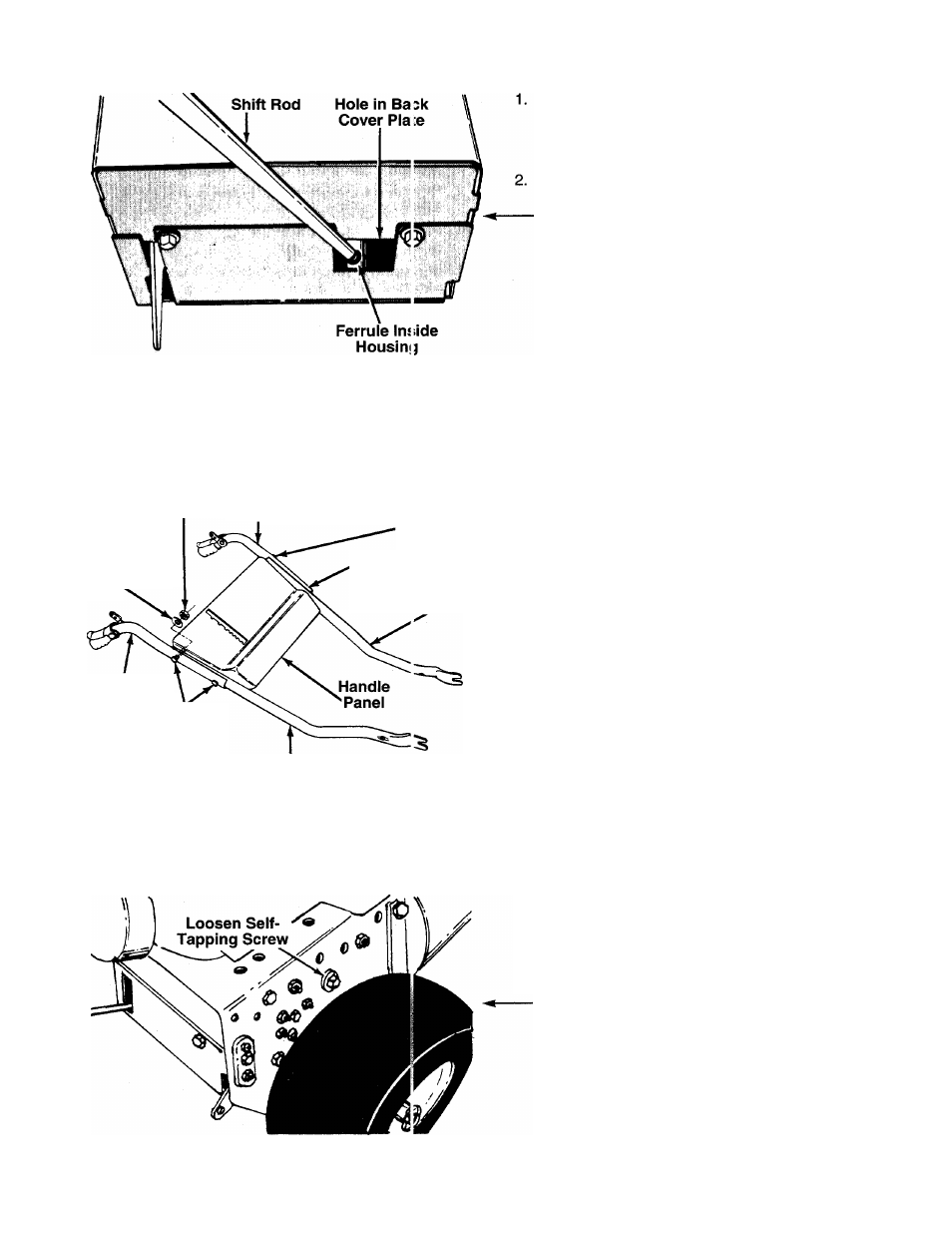
FIGURE 3.
Remove snow thrower and all parts from the car
ton. Check all carton inserts to be certain that all
loose parts and literature have been removed
before the carton is discarded.
Attach the shift rod to the shifting mechanism,
located inside the snow thrower frame, as follows.
■See figure 3.
a.
Place the threaded end of shift rod into the
hole in the back cover.
b. Thread the shift rod into the ferrule which is
attached to the shifting mechanism until the
ferrule is approximately halfway down the
threaded end of the rod. Adjustment of shift
rod will be made in step 17.
NOTE: The shift mechanism is a movabie assembly.
It may be helpful to pull the linkage (and ferrule) clos
er to the opening in the back cover when assembling
the shift rod.
Hex Nut
(C)
Left Hand
Upper Handle
Belleville
Washer (D)
Right
Hand
Upper
Handle
Carriage
Bolt (S)
Carriage
Bolts (S)
Leave Open
Left I-land
Lower Handle
Right Hand
Lower Handle
Preassemble the handles to the handle panel as
follows. See figure 4.
a. Place two carriage bolts (S) through the right
hand upper and lower handles (both carriage
bolts go through both handles).
Attach right hand handles to handle panel by
placing carriage bolts through the holes in the
handle panel.
Secure with two belleville washers (D) (cupped
side of washer against the handle panel) and
hex nuts (C). Do not tighten at this time.
Attach the left hand upper and lower handles
in the same manner, using only one carriage
bolt, belleville washer and hex nut in the
upper
hole
on the handle panel. Leave bottom hole
open.
b.
c.
-d.
FIGURE 4.
4. To attach the handle assembly to the unit, loosen
one self-tapping screw and belleville washer on
each side of the unit. See figure 5. A 9/16”
wrench or adjustable wrench is required.
FIGURE 5.