Ahaching the beam support/latch bracket, Attaching the engine and pump assembly, Attaching the control handle – MTD 242-630-000 User Manual
Page 7: Attaching the hoses, Final assembly
Attention! The text in this document has been recognized automatically. To view the original document, you can use the "Original mode".
Beam Support/
Latch Bracket
Hex Bolt
FIGURE 7.
Cylinder
FIGURE 9.
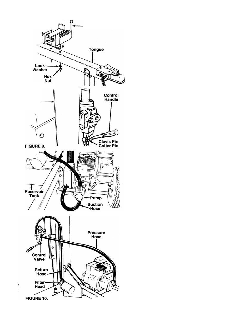
AHACHING THE BEAM SUPPORT/LATCH BRACKET
1. Remove the two hex bolts, lock washers and hex
nuts from the tongue, using two 9/16" wrenches.
2. Place the beam support/latch bracket on the
-------tongue as shown in figure 7. Secure with hex
bolts, lock washers and hex nuts just removed.
Tighten securely.
ATTACHING THE ENGINE AND PUMP ASSEMBLY
1. Using two 1/2" wrenches, remove the four hex
bolts, lock washers and hex nuts which secure
the base of the engine to the bottom of the ship
ping carton.
2. Place the engine and pump assembly in position
on the side of the reservoir tank assembly as
shown in figure 6. Secure with hardware just
removed. Tighten securely.
ATTACHING THE CONTROL HANDLE
^—1. The control handle is taped to the stripper half for
shipping purposes only. Remove the tape.
2. The bottom of the control handle is already
attached to the valve. Remove the cotter pin and
clevis pin which are attached to the valve. Place
the handle in position, and secure to the valve
using the cotter pin and clevis pin. See figure 8.
ATTACHING THE HOSES
Suction Hose
1. The suction hose is attached to the reservoir
^-------- tank. See figure 9. Loosen the hose clamp on the
free end of the hose using a screwdriver.
2. Attach the end of the hose to the fitting on the
bottom of the pump. Place the hose clamp at the
base of the fitting, and tighten securely.
Return Hose
1. The return hose is attached to the top of the
valve. Loosen the hose clamp on the free end of
the hose using a screwdriver.
2. Attach the end of the hose to the fitting on top of
-------the filter head. See figure 10. Place the hose
clamp at the base of the fitting, and tighten
securely.
Pressure Hose
The pressure hose is attached to the top of the pump.
Route the hose as shown in figure 10. Secure the
pressure hose to the bottom of the control valve,
using an adjustable wrench.
FINAL ASSEMBLY
1. Make certain all nuts, bolts and hose clamps are
tightened securely.
2. Before operating the log splitter, make certain to
follow “Initial Preparation” instructions.