5 main circuit breaker, 6 engine protective devices, 4 , automatic system operation – Generac Power Systems GUARDIAN 04137-0 User Manual
Page 7
Attention! The text in this document has been recognized automatically. To view the original document, you can use the "Original mode".
Section 1 — Generai Information
Guardian Liquid-cooied 8 kW Generators
GENERAL
INFORMATION
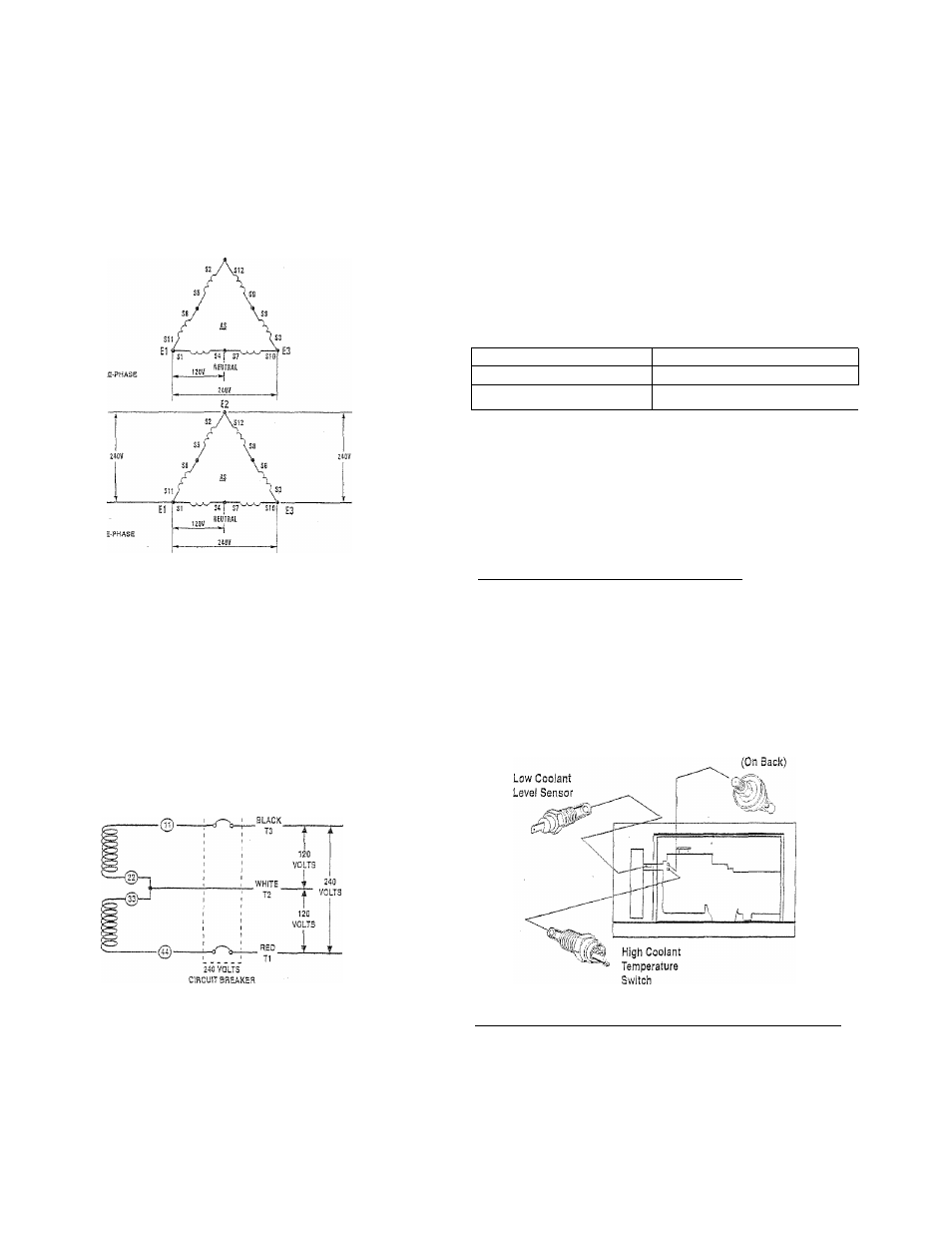
Figure 1.2 - Single- and Three-phase Delta
Generator AC Connection System
Figure 1.3 represents a single-phase, threenvlre
generator AC connection system. The stator assem
bly in this system consists of a pair of stationaiy
windings with Pan leads brought out of each wincl-
ing. Each single nhnding can supply a 120-volt, 60-
Hertz AC output. When the two windings are con
nected in series, a 240-volt, 60-Hertz AC output
results. Typically, the two "hot” leads in the circuit
are Wires 11 and 44. The neutral leads are the
junction of Wires 22 and 33.
Figure 1.3 - Single-phase
Generator AC Connection System
When utility source voltage has been restored, the
switch transfers back to the utility source voltage,
and the generator then shuts down,
1.5
MAIN CIRCUIT BREAKER
The generator’s main circuit breaker is included with
the unit as shipped from the factory. The breaker for
each unit is described as follows:
Mode! Number
Circuit Breaker Ratinq
04135-0
35A-2P-BQ2
04137-0
35A-3P-BQ3
1.6
ENGINE PROTECTIVE DEVICES
The engine has several safely switches tliat cause
it to automatically shut down under the following con
ditions: low oil pressure, high coolant temperature,
low coolant level, and engine overspeed or overcrank.
See Figure 1.4 for the location of these devices.
4 1.6.1 LOW Oil PRESSURE SWITCH________________
This switch is normally closed {N.C.] but is held open
by engine oil pressure during engine running. Should
operating oU pressure drop below apprommately 15
psi, the switch contacts close, and die engine shuts
down automatically.
Figure 1.4 - Engine Protective Devices
Low Oil
Pressure Switch
1.4 , AUTOMATIC SYSTEM OPERATION
Wnen this generator, along with its transfer switch,
has been Installed and interconnected, a circuit
board in the generator panel continuously monitors
utility power source voltage. Should that voltage
drop below a preset value, and remain at such a low
state for a preset amount of time, the generator
cranks and starts. After the generator starts, the
transfer switch transfers load circuits so the genera
tor can power them.
4 1.6.2 HIGH COOLANT TEMPERATURE SWITCH
This normally open (N.O.) thermostatic switch has
a sensing tip that is immersed in captive coolant.
Should the coolant temperature exceed approzd-
mately 124° C (256° F), the switch contacts close,
wTich causes the engine to shut clown automatically.
Generac® Power Systems, !nc.