Generac Power Systems GUARDIAN 04137-0 User Manual
Page 10
Attention! The text in this document has been recognized automatically. To view the original document, you can use the "Original mode".
OPERATION
(jo
Section 2 - Operation
Guardian Liquid-cooled 8 kW Generators
2.1
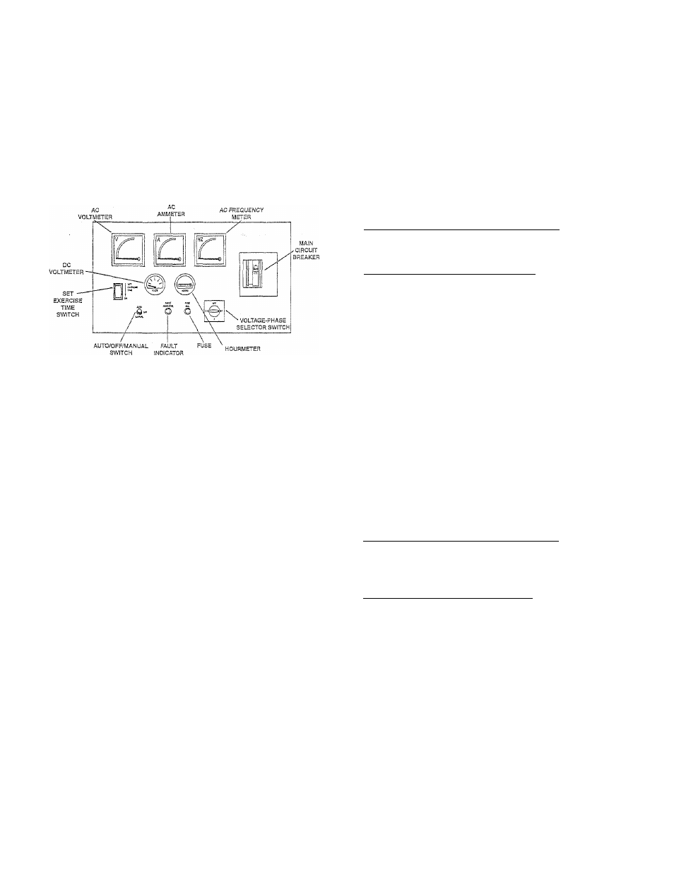
CONTROL CONSOLE COMPONENTS
The components of a liquid-cooled generator con
trol console (Figure 2.1) are as follows:
Figure 2.1 - Control Console
# 2.1.5 HGURMETER
♦ 2.1.1 AC VOLTIVI EIER
The voltmeter displays generator AC output voltage
during operation. Voltage is regulated by a solid-
state voltage regulator and is proportional to AC
frequency. Refer to your unit's DATA PLATE for
rated AC voltage.
4 2.1.2 AC AMMETER
This indicates current draw of connected electrical
loads during operation. DO NOT EXCEED YOUR
UNIT’S RxCTED MAXIMUM CONTINUOUS CUR
RENT. Refer to th,e unit DATA PLATE.
# 2.1.3 AC FREQUENCY METER
This indicates generator AC output frequency in
Hertz (cycles per second). Frequency is proportion
al to engine speed. Units vlth a four-pole rotor sup
ply 60 Hertz at 1,800 rpm. The frequency reading
with no electrical loads connected (no-load condi
tion) should be between 61-6.3 Hertz. With full
rated wattage/amperage load applied to the gener
ator, frequency should not droop below approxi
mately 58 Hertz.
♦ 2.1.4 DC VOLTMETER
The generator is equipped with a belt-driven DC
alternator, which maintains batten/ state of charge
when the engine operates. The control module
assembly also incorporates a triclde charge circuit
that maintains battery state of charge during non
operating periods. Battery voltage should read
approximately 12.5 to 14.5 volts DC. A low battery
voltage indicates the battery is discharging.
This indicates the time the engine-generator has
operated, in hours and tenths of hours. Use the
hourmeter along with the periodic maintenance
schedule for your generator set.
» 2.1.6 AUTO/OFF/MANUAL SWITCH______________
See Section 2.3.
» 2.1.7 FAULT INDICATOR LAMP___________________
This lamp goes ON when one or more of the following
engine faults occurs and when engine shuts down.
<> Low oil pressure « High coolant temperature
® Low coolant level ® Overcrank
» Overspeed
♦ 2.1.8 30-AiVIP FUSE
This fuse protects the contrcd console’s DC control
circuit against electrical overload. If the fuse has
melted open because of an overload, engine crank
ing and start-up cannot occur. Should you need to
replace the fuse, use only an identical 30-amp
replacement fuse.
» 2.1.9 VOLTAGE-PHASE SELECTOR SWITCH
This switch permits you to select either line-to-llne
or line-to-neutral voltage and amperage readings
on the console AC voltmeter and ammeter.
♦ 2.1.10 SET EXERCISE TIME SWITCH______________
This switch allows you to program the generator to
start and exercise automatically.
4 2.1.11
MAIN
CIRCUIT BREAKER___________________
The generator’s main circuit breaker is included
with the unit as shipped from the factory. See
“Main Circuit Breaker." Section 1.5 (Page 5), for the
appropriate breaker.
2.2
PREPARATION BEFORE START-UP
Before starting the generator, check that oil,
coolant
and
fuel
levels
are
correct
(see
“Specifications,” Section 1.7, Page 6).
2.3
USING THE AUTO/OFF/MANUAL
SWITCH
♦ 2.3.1 "AUTO" POSITION
vSelecting this switch position activates fully automat
ic system operation. It also allows the unit to start
and exercise the engine every seven days with the set
ting of tire exercise timer (see Section 2.7, Page 10).
Gensrac* Power Systems, ine.