A- a – Generac Power Systems GUARDIAN 04137-0 User Manual
Page 6
Attention! The text in this document has been recognized automatically. To view the original document, you can use the "Original mode".
GENERAL
INFORMATION
Section 1 — General Information
Guardian Liquid-cooied 8 kW Generators
1,1
UNPACKlNG/iNSPECTiON
After unpacldng, carefully inspect the contents
for damage.
« This standby generator set has been factory
installed in an all-weather, metal enclosure that
is intended exclusively for outdoor installation.
-A WARNING A-
A
lf this generator is used to power electrical load
circuits normally powered by a utility power
source, you are required by code to install a
transfer switch. The transfer switch must effec
tively isolate the electrical system from the util
ity distribution system when the generator is
operating (NEC 701). Failure to isolate an elec
trical system by such means will result in dam
age to the generator and also may result in
injury or death to utility power workers due to
backfeed of electrical energy.
If. any loss or damage is noted at time of delivery,
have the person(s) making the delivery note all
damage on the freight bill or affix his or her signa
ture under the consignor's memo of loss or damage.
If you note loss or damage after delivery, separate
the damaged materials and contact the carrier for
claim procedures.
“Concealed damage” is understood to mean damage
to the contents of a package that is not in evidence
at the time of delivery, but is discovered later.
# 1.1.1 LIFTING THE GENERATOR
-A
WARNING
A-
A
When lifting or hoisting equipment is used, be
careful not to touch overhead power lines.
A
The generator's weight of more than 1,500
pounds requires proper tools and equipment,
and qualified personnel to be used in all phases
of handling and unpacking.
1.2
THE GENERATOR ..
This
liquid-cooled,
Guardian
generator
set
is
designed to supply electrical power to operate criti
cal electrical loads during utility power failure. The
unit has a four-pole revolving field (rotor) and uti
lizes long-life brushes and slip rings to deliver exci
tation current to the rotor windings. The rotor is
directly connected to the engine shaft by a high-
strength flexible disc. The engine governor holds
the diesel engine and rotor speeds at a constant
factory setting of approximately 1,860 rpm.
Use this generator as a source of electrical power
for tlie operation of 120- and/or 240-volt, single-
or three-phase loads; or 120- and/or 208-volt,
three-phase loads.
These models are available, rated as follows;
04136- 0: Provides 8,000 watts (8 kW) of single
phase power.
04137- 0: Provides 8,000 rvatts (8 kVV) of three-
phase power.
1.3
GENER.ATORAC
CONNECTION SYSTEMS
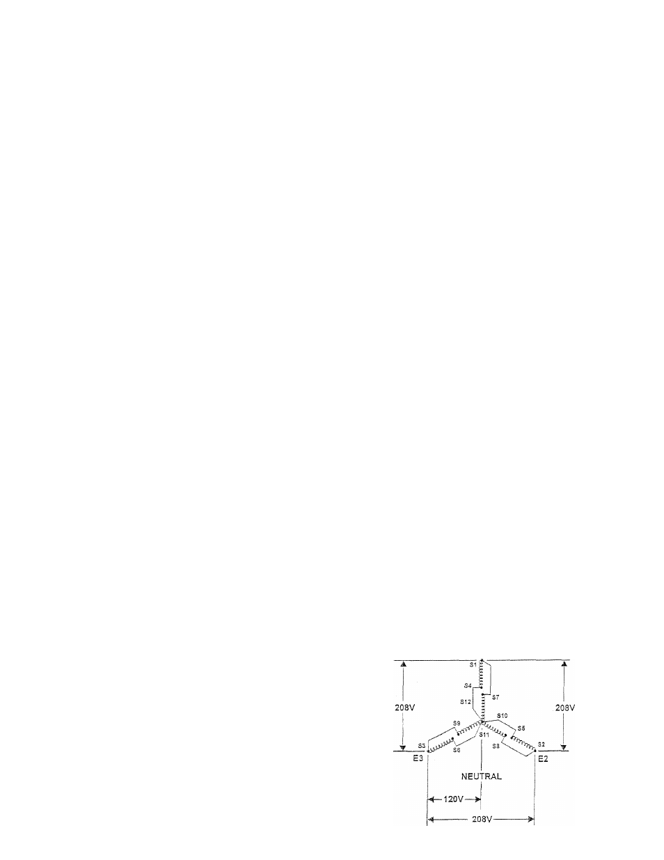
Ttie three-phase generators are shipped from tlie fac
tory with their stator AC output leads connected in a
12-lead low we configuration (Figure 1.1). This tyq)e
of connection system wül supply a 120- and/or 208-
volt, three-phase output as showm in tire illustration.
If, however, load voltage requires a 120/240-voIt,
single- or three-phase output, the stator's output
leads will need to be reconnected (Figure 1.2). This
task should be performed only by a qualified
Generac/Guardian Authorized Technician. Refer to
the Guardian Installamn, Start-up and Adjustment
Manual (Part No, 79699) for details.
Figure 1.1 - 12-!ead Low Wye
Generator AC Connection System
E1