Travel pedal adjustment, Hydrostatic neutral adjustment, A warning – Troy-Bilt GTX 20 User Manual
Page 24: A caution, Incorrect adjustment may damage pin, Maintenance (continued)
Attention! The text in this document has been recognized automatically. To view the original document, you can use the "Original mode".
Maintenance (continued)
Hydrostatic Maintenance and
Lubrication (continued)
3.
When transmission is cold, check
fluid level in transmission. Fill to the
level indicated on dipstick, located
beneath seat.
Transmission Oi! Filter:
Replace
transmission oil filter every 100 hours.
Filter is located under tractor, in front of
transmission. See parts catalog for part
number and part ordering information.
For more detailed hydrostatic maintenance
information, a separate repair manual is
available from your dealer.
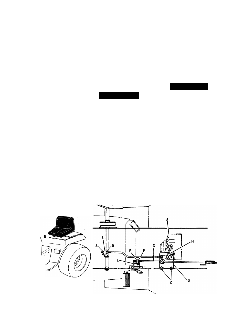
Travel Pedal Adjustment
The travel pedal was adjusted at the
factory with tip (of pedal) approximately
45° forward of vertical center line. This
angle can be adjusted for comfort:
1.
Loosen hex nuts (A, Fig. 7-9).
2.
Adjust hex nuts until desired angle is
reached.
3.
Retighten nuts (A) against rod end
(L).
Hydrostatic Neutral Adjustment
Hydrostatic neutral is adjusted at factory.
If tractor creeps forward or backward
while hydrostatic pedal is in neutral
position, adjust as follows:
1. Securely block up rear of tractor so
rear wheels clear ground.
A WARNING
USE EXTREME CARE WHEN JACKING OR
HOISTING TRACTOR. BLOCK WHEELS
AND USE JACKSTANDS TO SECURELY
HOLD UNIT IN PLACE.
2.
Remove tractor chassis tunnel (B,
Fig. 7-9) by removing the four screws
indicated.
3.
Start engine and release brake.
4.
Loosen capscrews (C). Move
support plate (D) forward if wheel
rotates in a forward direction or
move support plate toward the rear if
it rotates in reverse.
5.
Tighten capscrews (C) when wheels
no longer rotate.
6.
Stop engine and lock brake arm
against stop (E).
7.
Loosen jam nuts (F) and turn rod (G)
until pin enters slot (H) of neutral
plate. Adjust until there is a gap of
1/32" between end of slot and pin.
A CAUTION
INCORRECT ADJUSTMENT MAY
DAMAGE PIN.
8.
Tighten jam nuts (F).
9.
Re-install chassis tunnel (B). Secure
with screws removed earlier.
Remove screws
for access into
chassis tunnel.
Fig.7-9
24