Figure 19, Remote control deflector - figure 20, Figure 21b – Ariens 924071 User Manual
Page 15: Discharge chute & deflector cable - figure 21, Deflector adjustment - figure 21, Runners - figures 22 & 2, Figure 21, Tire pressure, Assembly & pre-service
Attention! The text in this document has been recognized automatically. To view the original document, you can use the "Original mode".
ASSEMBLY & PRE-SERVICE
CLEVIS
SETSCREW
\\\
71
BELL CRANK
SLIDER
ROLLER
CLEVIS
SETSCREW
AnACHMENT
CLUTCH
ROD
FIGURE 19
REMOTE CONTROL DEFLECTOR - FIGURE 20
Install the bracket of the Remote Control Deflector
assembly to the upper left portion of the handlebar
panel with screws .and nuts securing the upper
handlebars to the lower handlebar and panel asembly.
REMOTE
DEFLECTOR
CONTROL
BRACKET
REMOTE
CONTROL
DEFLECTOR
CABLE
REMOTE DEFLECTOR
CONTROL KNOB
SCREWS
AND NUTS
HANDLEBAR
— PANEL
FIGURE 20
ENGINE
BOLT
BELT
COVER
COTTER PIN
DEFLECTOR
CABLE
REMOTE CONTROL
DEFLECTOR RETAINER
REMOTE CONTROL
DEFLECTOR
CABLE
FIGURE 21A
DEFLECTOR
BRACKET
JAM NUT
CHUTE BRACKET
\
FIGURE 21B
DISCHARGE CHUTE & DEFLECTOR CABLE - FIGURE
21
The Deflector and discharge chute are assembled and
shipped with the four mounting clips attached to the
chute. Remove the clips and hardware. Position the
discharge chute on the blower housing. Secure with
the clips and hardware. Be sure the chute rotates free
ly. Route remote deflector cable through the retainer
mounted to the engine as shown in Figure 21 A. Install
deflector cable as shown in Figure 21B to Deflector and
discharge chute. Use jam nuts on cable to secure cable
to chute bracket and cotter pin to attach cable to
bracket on deflector.
DEFLECTOR ADJUSTMENT - FIGURE 21
To adjust the deflePtor cable for correct travel distance
of deflector loosen the jarn nuts securing the deflector
cable to the bracket on the chute. Set Deflector in
lowest position. Then tighten jam nuts. Be sure also to
check movement of Deflector to highest position.
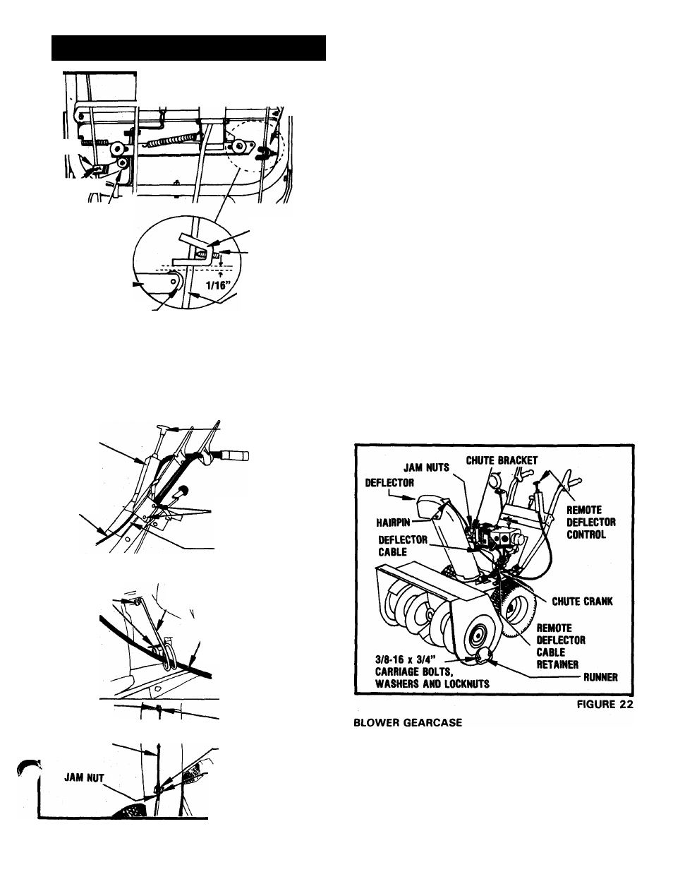
RUNNERS - FIGURES 22 & 2
Install runners on each side of the blower housing. Use
longer carriage bolts (6201 3) in the rear holes, shorter
carriage bolts (62010) in the front holes. Use a washer
(64002) and locknut (65039) on each bolt outside the
housing. Adjust the runners to equal height on each
side. See "ADJUSTMENTS-MAINTENANCE” section
of this manual.
FIGURE 21
Check the oil level in the blower gearcase. Oil level
must be even with the oil filler hole. Fill with Ariens
Special L-2 Gear Lubricant. Replace the filler plug. See
"LUBRICATION” section of this manual.
TIRE PRESSURE
Tires have been under inflated for shipping purposes.
For operation, increase tire pressure to 1 2 to 20 PSI. If
- 15 -