Assembly & pre-service – Ariens 924071 User Manual
Page 13
Attention! The text in this document has been recognized automatically. To view the original document, you can use the "Original mode".
ASSEMBLY & PRE-SERVICE
WARNING: FAILURE TO FOLLOW ALL INSTRUCTIONS
FOR ASSEMBLY AND PRE-SERVICE COULD RESULT
IN PERSONAL INJURY AND/OR DAMAGE TO THE
SNO-THRO. CHECK AND TEST THE FUNCTION OF
ALL CONTROLS BEFORE STARTING ENGINE. BE SURE
TO FILL ENGINE WITH OIL.
WARNING: ALL ASSEMBLY AND ADJUSTMENT PRO
CEDURES ARE TO BE MADE WITH ENGINE STOPPED
AND SPARK PLUG WIRE DISCONNECTED.
NOTE: MAKE SURE ALL SAFETY DEVICES AND
GUARDS ARE IN POSITION AND OPERATING PROPER
LY. READ "INSTRUCTIONS FOR SAFE OPERATION"
BEFORE USING UNIT.
GENERAL
All hardware and parts required for assembly are ship
ped in the parts bag or are located, in place, on the
machine. The upper handlebars and panel are assem
bled at the factory with the two clutch rods and in
terlock system in place and adjusted. The lower
handlebars must be installed. The snow head and trac
tor are shipped assembled with lower shift rod in place.
Attachment clutch rod is in place on handle panel
ssembly.
Handlebar Assembly, Deflector and Discharge Chute,
Runners, Remote Deflector Control and Headlight must
be attached.
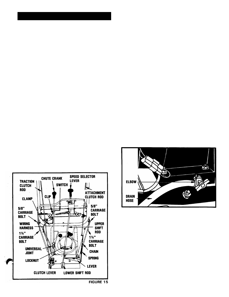
HANDLEBAR - FIGURES 15 & 22
Install the lower handlebars on the frame using the
studs and hardware in place on the frame. (Leave the
hardware loose on the studs until the upper handlebars
are installed). Be sure to install the chute crank bracket
on the left rear stud of handlebar when installing
handlebar. See "CHUTE CRANK" instructions.
Install the upper handlebar and panel on the lower
handlebars. Use a 5/8" carriage bolt and locknut in
each of the top holes, and a 1-1/2" carriage bolt and
locknut in each of the lower holes. With everything in
place, tighten all handlebar hardware.
ENGINE - FIGURES 1 & 16
1.
Remove oil drain plug from the right hand side of
engine base. Install reducer and elbow and tighten
until elbow outlet is toward rear of machine. In
stall drain hose with clamp onto elbow. See Figure
16. Remove plastic cover on oil fill tube and
discard.
2.
Add oil according to engine manufacturer's in
structions provided with the Sno-Thro. After fill
ing crankcase, insert dipstick into the oil fill tube.
See Figure 1. The dipstick is shipped with loose
parts in the parts container.
3.
Install throttle control knob from parts bag by
screwing it onto the rod protruding through the
top of the engine. See Figure 1.
FIGURE 16
CHUTE CRANK - FIGURES 15 & 17
The chute crank is packed separately in the carton. The
intermediate shaft, universal joints and chute crank
bracket are in place on the machine. The chute crank
bracket should be re-installed on the rear, left hand stud
at the time the handlebars are installed. Insert the chute
crank down into the hole in the handlebar panel and
connect to the universal joint on the intermediate shaft
with the hairpin cotter provided. See Page 12 illustra
tion also. After completing the chute crank connection,
check the alignment of worm and chute by rotating the
discharge chute through its full travel. (lihute should
rotate easily. If not, reposition worm as required and
adjust according to "CHUTE CRANK ADJUSTMENT"
instructions
in
"ADJUSTMENTS-MAINTENANCE"
section of this manual.
- 13 -