Ariens 931015 S-18 User Manual
Page 14
Attention! The text in this document has been recognized automatically. To view the original document, you can use the "Original mode".
REAR WHEEL TREAD ADJUSTMENT
The rear wheels are normally assembled in the narrow
tread position, shown in Figure 25. The wheels can be turned
on the hubs for a wider tread. The wide tread provides greater
stability on hillsides and on rough terrain.
Remove the wheel lug nuts, turn the wheels around with
the valve stems inward and re-assemble on the hub.
NARROW WHEEL TREAD SETTING
(23
X
10.50
X
12 TIRES SHOWN)
Æ
_•_
^
narrow
‘
s
23x 10.50 X 12 » 32'A
WIDE H
23 X 10.50 X 12 » 35V4
FIGURE 25
If Chevron tread tires are used, remove the wheel lug
nuts and re-assemble the wheels on opposite sides of the
tractor with the valve stems turned inward. I nterchanging
'the wheels is necessary to maintain proper direction of
rotation for traction tires.
HYDRAULIC LIFT OPERATION
The hydraulic control lever is located on the control
console, shown in Figure 2. It is a four position lever to per
form four functions, UP, HOLD, DOWN and FLOAT. The
normal out-of-use position is. the "HOLD" position and
the attachment will not lower or raise. When it is desired to
raise the attachment, the lever is pulled to the "UP" po
sition and the cylinder is actuated to lift the attachment.
When the lever is moved to the "DOWN" position, the oil
pressure in the cylinder is reversed and the cylinder forces
the attachment down.
When an attachment is being used which is designed to fol
low ground contours, the lever should be placed in the
"FLOAT" position.- The cylinder is then free to move as the
attachment position requires.
Figure 28 shows the components of the hydraulic lift
system. The hydrostatic transmission charge pump supplies
the oil flow from the rear axle transmission oil reservoir. Oil
flow to and from the cylinder is controlled by the valve. The
back end of the cylinder is anchored to the rear rock shaft.
The forward end of the cylinder is pinned to the lower end
of the bell crank.
When the cylinder is extended or retracted, the bell crank
pivots and raises or lowers both the front and center rock
shafts at the same time through the front and center rock
shaft linkages shown in Figure 28. The connection to the
center rock shaft is made through the slotted hole which allows
the center rock shaft to move up and down, allowing the
mower to float independent of the flotation provision in
the hydraulic system.
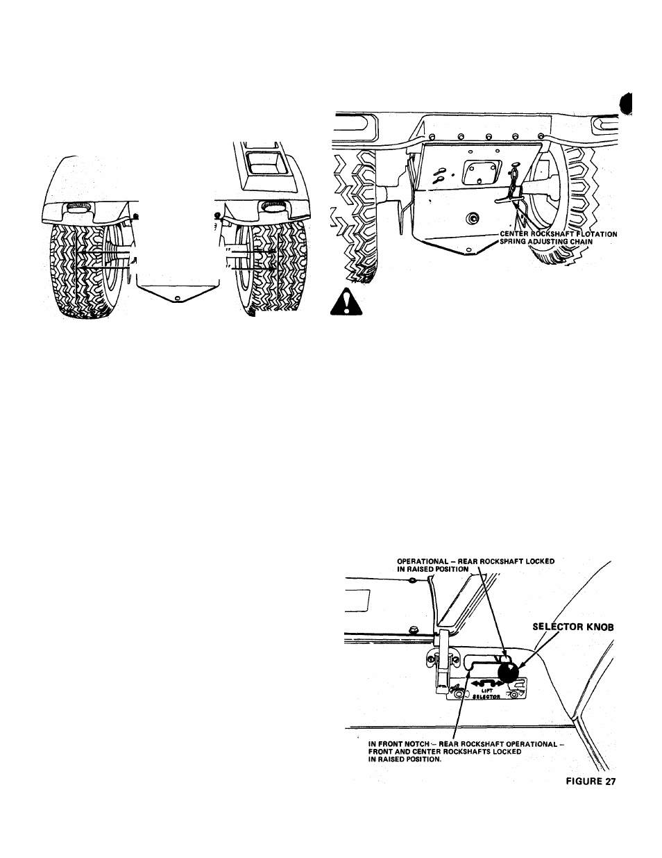
The center rock shaft flotation spring provides mower
flotation. The tension on the spring can be increased by pulling
the chain shown in Figure 26 and latching a chain link in the
notch in the back of the tractor frame. This spring should
always be in use when the mower pan is used.
FIGURE 26
CAUTION - WHEN ADJUSTING CHAIN TENSION ALWAYS GRASP
CHAIN HANDLE FIRMLY (NOT THE CHAIN) AS CONSIDERABLE TENSION
IS ON THE CHAIN AND INJURY TO THE HANDS COULD RESULT.
HYDRAULIC LIFT REAR ROCK SHAFT
The tractor comes with a lift selector device so that
the front and center rock shafts can be operated in
dependently of the rear rock shaft while utilizing only one
hydraulic cylinder. The alternately latched, split lift linkage
system holds the front and center rook shafts in their raised
positions while the rear rock shaft is operated by the cylinder
or vice versa. This allows a rear mounted attachment to be
used without removing the front pr center mounted attach
ments and vice versa.
€
To make the rear rock shaft operational, move the hy
draulic control lever to the "UP" position and hold it there
uritil the cylinder is fully extended. Place the selector knob in
the front notch (Figure 27).
To make the front and center rock shafts operational,
move the hydraulic control lever to the "UP" position and
hold it there until the cylinder is fully extended. Place the
selector knob in the rear notch as shown in Figure 27.
IN REAR NOTCH - FRONT AND CENTER ROCKSHAFTS
- 1 4 -