Ariens 931015 S-18 User Manual
Page 11
Attention! The text in this document has been recognized automatically. To view the original document, you can use the "Original mode".
Ariens dealers will provide any service which may be
required to keep the tractor operating at peak efficiency. The
tractor is equipped with the finest quality engine obtainable.
However, should servicing be required, it can be obtained
from an Ariens dealer or an authorized engine manufacturer's
service station. Consult your Ariens dealer for details.
SEAT ADJUSTMENT
The seat is adjustable forward and backward to seven
positions. To adjust seat position, grasp seat back and raise
%at. Slide the seat forward or backward as required to the
most comfortable position.
HYDROSTATIC CONTROL ADJUSTMENT
If the tractor creeps when the hydrostatic control lever is
in the neutral (N) position on the control console, make the
following adjustment;
I
The hydrostatic controls should be adjusted so the tractor
does not creep forward or backward when the control lever
in the neutral (N) slot in the control console as shown
Figure 2. In addition, the control lever should automatically
be shifted to this position from either “forward" or "reverse*'
when the neutralizer pedal is ^Hy depressed.
CAM SLOT
CAUTION:
REAR AXLE MUST BE RAISED
AND
BLOCKED
SECURELY
SO
THAT
REAR
WHEELS ARE FREE TO REVOL VE.
ì
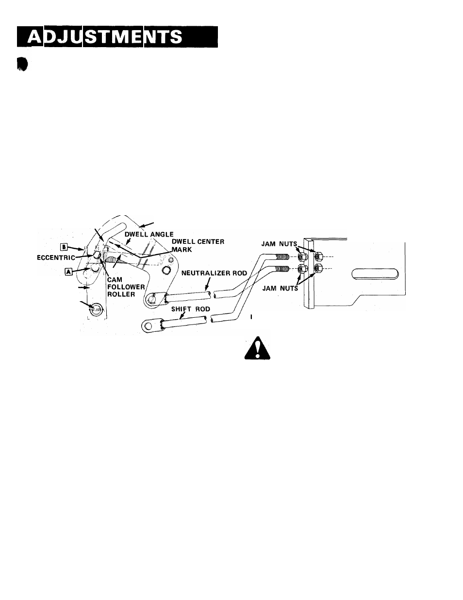
2. Loosen clamp bolt B, Figure 18 and rotate the eccentric
until the flats on the eccentric are parallel to the cam slot as
shown in Figure 18. Retighten bolt B. This will assure a
maximum fine adjustment range.
3. With the control fork. Figure 19, move the cam. Figure
18, until the cam follower roller is lined up with the cam
dwell center mark. DO NOT adjust the hydrostatic control
fork. Figure 19, if the control lever is not in the neutral slot
of the console. This is the final adjustment to be made.
4. Depress free-wheeling valves by rotating cam up. See
Figure 6.
5. Loosen pintle lever clamp bolt A, Figure 18, a sufficient
amount to allow the pintle lever to move freely. Move the
hydrostatic còntrol lever. Figure 19, in the park-start position,
start the engine and run at idle. Return the control lever to
the neutral slot in the control console.
6. Release the free-wheeling valves by rotating cam down.
Figure 6. NEUTRALIZER PLATE
PINTLE LEVER
PINTLE SHAFT
LLUSTRATED AS VIEWED
FROM RIGHT HAND SIDE OF MACHINE
FIGURE 18
1. Jack up the rear of the tractor until the drive wheels clear
the ground and BLOCK SECURELY. Wheels must be free to
revolve.
2. With the control lever in "park-start" position, raise the
rear deck. Activate seat switch to allow engine to start.
3. Start engine; place control lever in the neutral position and
increase engine speed to full throttle.
4.
Loosen clamp bolt B, Figure 18 a sufficient amount
to allow the cam follower to rotate. Turn the eccentric
"clockwise" or "counter-clockwise" as required until the
rear tractor wheels completely stop. Retighten clamp bolt B.
Check adjustment by moving the control lever to both
forward and reverse positions several times. Each time the lever
is returned to neutral, the rear wheels should stop com
pletely if they drift, re-adjust the eccentric until a true neutral
position is found.
A
CAUTION:
USE
EXTREME
CAUTION
WHEN
AD
JUSTING
THE
HYDROSTATIC
LINKAGE
WITH
THE ENGINE RUNNING DUE TO THE ROTATING
DRIVE SHAFT COUPLING AND FAN.
If a positive neutral cannot be found by adjusting the
eccentric, it will be necessary to adjust the hydrostatic
linkage using the following procedure;
1
Use steps 1 and 2 of the previous-procedure.
-11-
CAUTION:
WHEELS
MAY
TURN
WHEN
FREE
WHEELING
CAM
IS
RELEASED.
KEEP
ARMS
AND LEGS CLEAR A T A L L TIMES.
Check that the cam follower roller is lined up with cam
dwell center mark. Move the pintle arm back and forth
until wheels stop turning. Carefully tighten bolt A, Figure 18.
The neutral adjustment is extremely sensitive and this pro
cedure is a course adjustment. If, when bolt A is tightened, the
wheels still move slowly, the fine tuning will be done in step 9.
7. Loosen (4) jam nuts on neutralizing plate. Figure 18, and
depress neutralizer pedal completely. Figure 3. The cam
follower roller. Figure 18, should remain in line with the cam
dwell center mark. Snug (4) jam nuts up against neutralizer
plate. Release pedal and securely tighten jam nuts.
8. Check the hydrostatic control lever. If the neutralizer
pedal does not automatically shift the control lever to the
neutral position from either "forward" or "reverse" when
the pedal is fully depressed, loosen hydrostatic control fork
adjustment bolt D, Figure 19. Move the fork so that it aligns
with the neutral slot in the control console. Securely tighten
bolt D.
9. If the wheels still move slowly when neutralized, increase
the engine speed to full throttle. Loosen clamp bolt B,
Figure 18 and adjust the eccentric roller until the wheels
stop completely. Tighten clamp bolt B, Figure 18.