Ariens 931015 S-18 User Manual
Page 12
Attention! The text in this document has been recognized automatically. To view the original document, you can use the "Original mode".
CONTROL LEVER FRICTION ADJUSTMENT
The hydrostatic friction plates, shown in Figure 19, must
be adjusted so the control lever moves through the "forward"
and "reverse" modes with a minimum of force. However,
there must be sufficient spring pressure on the friction
plates so that, under normal operating conditions, the control
lever will remain at any selected setting.
If the tractor has a tendency to slow down or speed up
without touching the control lever, it will be necessary to in
crease the spring pressure on the friction plates by tightening
the screws at A and B, Figure 19. Access to these screws can
be gained by raising the rear deck of the tractor and inserting
a screw driver through the access holes as shown.
If the tractor has a tendency to speed up, tighten screw A
slightly more than screw B.
i
If the tractor has a tendency to slow down, tighten screw
B slightly more than screw A.
NOTE:
The
control
console,
see
Figure
19,
has
been
removed for clarity only.
.HANDCONTROL LEVER
When the mechanism is properly adjusted, the park-lock pin
will engage the teeth of the reduction gear when the
control lever reaches Point B, Figure 21, and the pin will
be completely disengaged at Point A.
FRICTION PLATES
HYDROSTATIC
CONTROL
FORK
CONTROL CONSOLE -
REMOVED FOR CLARITY
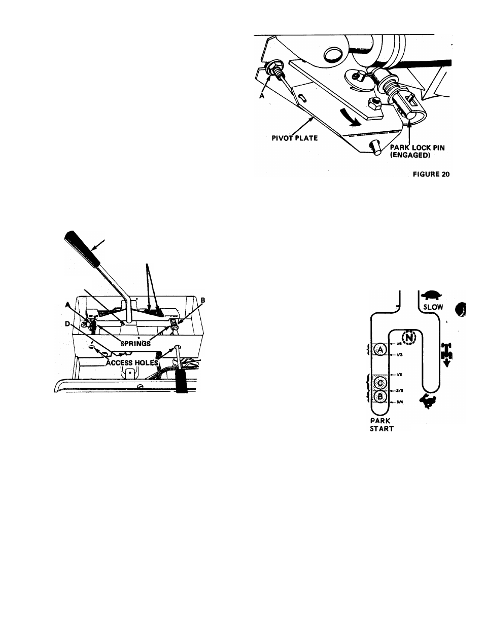
Adjustment is made by loosening
nuts A, Figure 20, and moving the
cable housing "in" or "out" until
the over-center latch actuates when
the control lever reaches Point C,
Figure 21, as the lever is moved
from the front of the slot, rear
ward into the park-start position.
Moving the cable housing "in" to
ward the tractor causes the park-
lock pin to engage later. Moving it
"out" away from the tractor causes
the pin to engage earlier in
the reduction gear.
FAST
4
X
PARK LOCK DISENGAGES
SCREWDRIVER
OVERCENTER LATCH ACTUATES
FIGURE 19
PARK LOCK MAINTENANCE AND ADJUSTMENT
PARK LOCK ENGAGES
When the hydrostatic control lever is placed in the "park-
start" position, the cable shown in Figure 20 is pushed out of
the cable housing causing the pivot plate to rotate in the di
rection of the arrow. This results in the park-lock pin engaging
in a reduction gear in the differential housing which locks the
rear wheels. When the control lever is moved forward, the
pivot plate rotates opposite to the direction of the arrow
shown in Figure 20 and the park-lock pin disengages from the
reduction gear thus unlocking the rear wheels.
FIGURE 21
PARK LOCK BRAKE ADJUSTMENT
The park lock brake must be adjusted to hold the control
lever at the rear of the "park-start" slot in the console. Other
wise, while starting the engine, the control lever will need to
be held back to fully depress the safety switch located under
the console cover.
The park-lock mechanism should be kept clean of any dirt
or grass build-up and the moving parts should be oiled
occasionally to assure that the park-lock functions properly.
The "park-lock" brake is adjusted by tightening or loosen
ing nut A, Figure 20;
FRONT WHEEL TOE-IN ADJUSTMENT
The park-lock mechanism is properly adjusted when the
over-center latch pin, Figure 20 actuates at Point C, Figure
2fl (approximately 1/2 to 2/3 the length of the slot on the
console cover), as the control lever is moved from the front
of the slot back into the park-start position. A distinct
"click" can be heard when the over-center latch actuates.
Proper toe-in of the front wheels is necessary to assure
proper steering and to reduce tire wear. The proper amount
of toe-in is when the front of the wheels are 1/16" to 1/8"
closer together than the rear of the wheels, measured at the
horizontal centerline of the rim flange.
-12-