Snow thrower operating controls, Note, Figure 11 – Sears 247.8867 User Manual
Page 7
Attention! The text in this document has been recognized automatically. To view the original document, you can use the "Original mode".
Choke Knob—Use FULL choke position to start a cold
engine.
Primer Button—Used to inject fuel directly into the car
buretor to insure fast starts in cold weather.
Ignition Key—Must be inserted into ignition key slot
to start engine. Pull out to stop. Do not turn ignition key.
Starter Handle—Used to manually start the engine. An
Electric Starter kit is available. See Engine Repair Parts
section of this manual tor kit number.
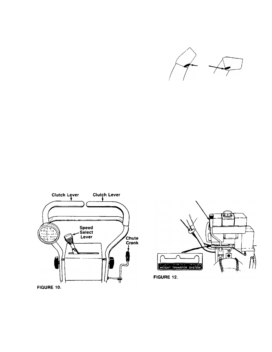
SNOW THROWER OPERATING CONTROLS
The snow thrower operating controls and their tunctions
are as follows (see figure 10):
Speed Select Lever—Located on the handle panel.
The speed select lever allows the operator to use one
of the six (6) forward speeds, neutral or reverse. To
shift, move the speed select lever to desired position.
NOTE
lever
Release the traction drive clutch
before shifting gears.
Traction Drive Clutch Lever—Located on the right
handle, the traction drive clutch lever is used to propel
the snow thrower forward or in reverse. Push lever
down to engage: release lever to disengage.
Auger Drive Clutch Lever—Located on the left han
dle, the auger drive clutch lever is used to engage and
disengage the auger and impeller. Push down to
engage; release to disengage.
Traction Drive Auger Drive
Discharge Chute—The direction snow is thrown can
be changed by turning the chute crank. See figure 10.
Turn clockwise to discharge to the left. Turn
counterclockwise to discharge to the right. The distance
snow is thrown can be adjusted by raising the discharge
chute for greater distance, or lowering for less distance.
See figure 11. Loosen the hand knob on the side of the
discharge chute to adjust. Pivot the chute to desired
position, and retighten hand knob.
Hand
Knob
/
FIGURE 11.
Weight Transfer Lever—Located on the right side of
the snow thrower. Move the lever away from the engine,
then forward or backward to select one of three posi
tions for operation. See figure 12.
1. Packed Snow—Shifts additional weight to the
snow thrower housing to keep the front end down
to the ground for hard-packed or icy snow con
ditions.
2. Normal Snow—Weight is distributed more evenly
for normal snow removal.
3. Light Snow—Weight is shifted toward the back of
the snow thrower. Use this position when clearing
a light snowfall, especially on gravel or uneven sur
faces. This is also the best position lor transport.
Weight
Transfer
Lever
Drive Wheels—The wheels may be adjusted for two
different methods of operation. The adjustment is made
by moving the “kwik" pin on the ends of the axle to
one of two different positions.
1. Dual Wheel Drive—For heavy snow, insert the kwik
pins into the wheel hubs for power drive to both
wheels. See figure 13.