Installing the headlight asssembly, Tire pressure, Final adjustments – Sears 247.8867 User Manual
Page 6: Operating instructions, Engine operating controls, A danger
Attention! The text in this document has been recognized automatically. To view the original document, you can use the "Original mode".
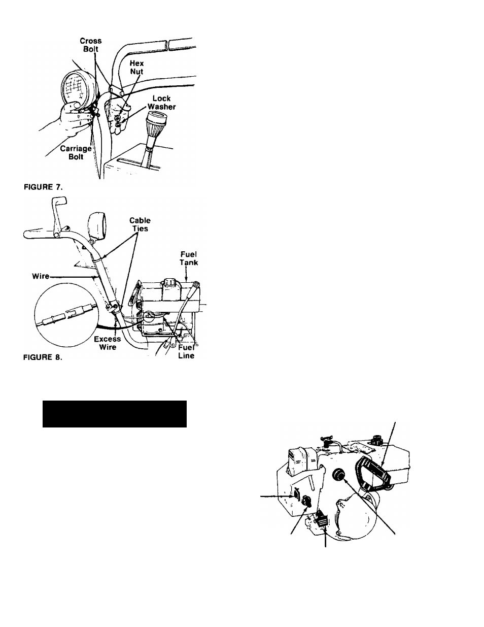
INSTALLING THE HEADLIGHT ASSSEMBLY
1. Insert the carriage bolt on the bottom of the
headlight assembly through the hole provided on
-------the right hand side of upper handle. See figure 7.
2. Secure with 5/16" lock washer and hex nut pro
vided in the headlight kit.
3. Pivot the headlight so it will illuminate the path to
be cleared. Tighten the cross bolt to hold the
headlight in this position. See figure 7.
4. Route the wire behind the handle panel and to the
inside of the handle as shown in figure 8. Route
it to the inside of the fuel line. Plug the wire from
the headlight into the wire lead on the engine
(located beneath the fuel tank).
5. Secure the wire to the upper handle using one
-------cable tie as shown in figure 8. Loop any excess
wire and attach it to the lower handle with the other
cable tie as shown.
TIRE PRESSURE
The tires are overinflated for shipping purposes. Check
the tire pressure, and reduce to 15 to 20 psi. The tire
pressure must be equal in both tires.
FINAL ADJUSTMENTS
Before operating the snow thrower, adjust the skid
shoes to accomodate the type of surface to be cleared,
and check the adjustment of the speed select lever.
Refer to Skid Shoe Adjustment and Speed Select Lever
Adjustment in Adjustments/Repairs section on page 12.
OPERATING INSTRUCTIONS
A DANGER
1. STOP ENGINE BEFORE REMOVING DEBRIS
AND SERVICING UNIT
2. KEEP CLEAR OF IMPELLER WHILE ENGINE
IS RUNNING
3. NEVER DIRECT DISCHARGE AT BYSTANDERS
OR WINDOWS OR ALLOW ANYONE IN FRONT
OF UNIT
4. THOROUGHLY INSPECT THE AREA WHERE
THE EQUIPMENT IS TO BE USED AND
REMOVE ALL DOOR MATS, SLEDS, BOARDS.
WIRES AND OTHER FOREIGN OBJECTS
5. REFER TO OWNERS MANUAL FOR FULL
INSTRUCTIONS
Ignition
Key
ENGINE OPERATING CONTROLS
The engine operating controls and their functions are
as follows (see figure 9);
Throttle Control Lever—Used to control speed of
engine.
Starter
Handle
Choke
Knob
Throttle
Control
Primer
Button
FIGURE 9.