S i m, R . to replace motion dri¥e belt fsee fig. 26), Transmission semoval/replacement – Sears 917.25759 User Manual
Page 21: Front wheel toejn/camber
Attention! The text in this document has been recognized automatically. To view the original document, you can use the "Original mode".
S i m
ì h i i ì
r .
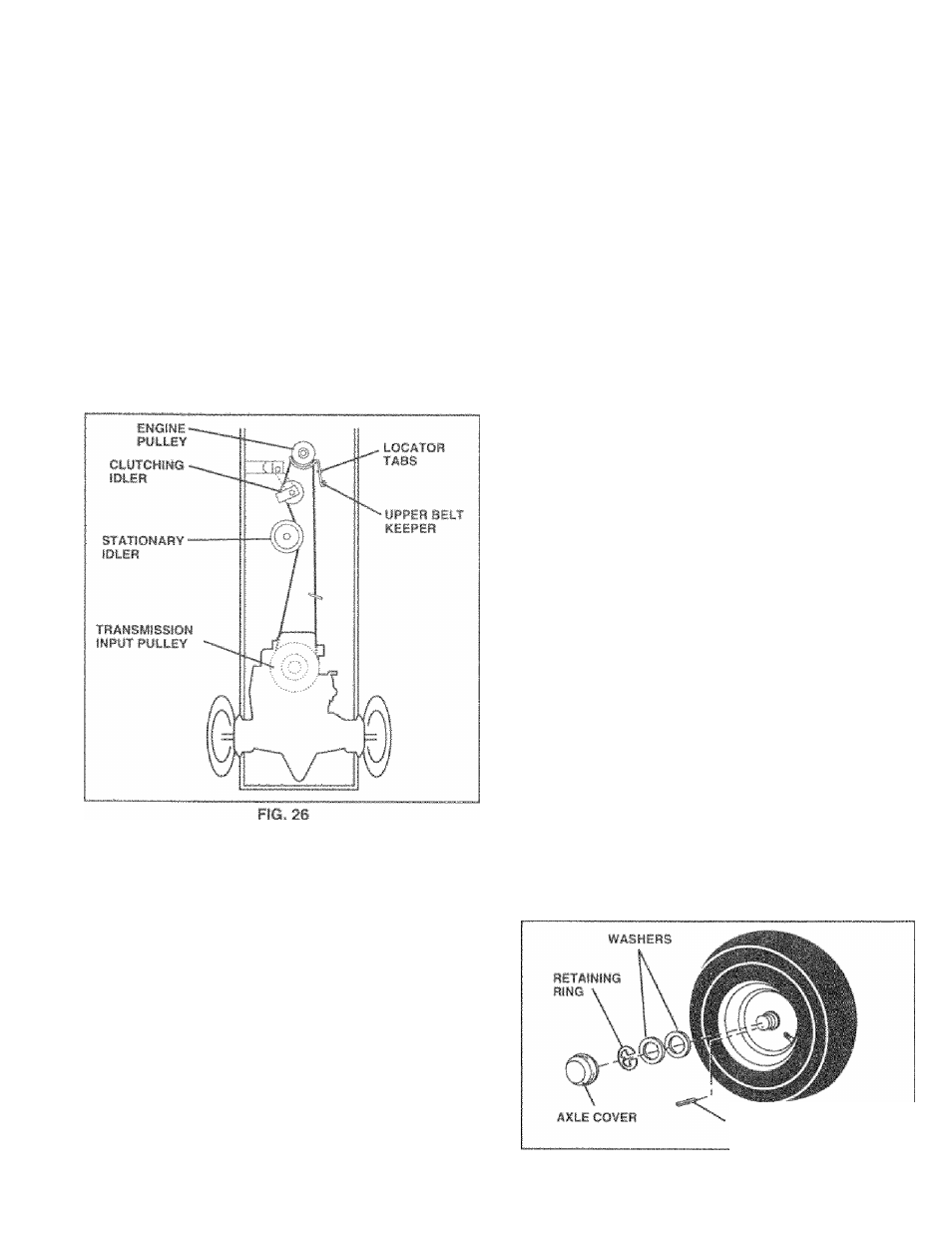
TO REPLACE MOTION DRI¥E BELT
fSee Fig. 26)
Pijrk ttif* tryctof on lev'.i f.urf.ico, tufjfi'jo pa;king SjfuKr?.
Far ¿inbi&tance, fharo is .n nrknilafiia’ guide r.lecai i.:n
bi>lti>rn
Side
u! left foofit'-el
*
•
flernove rnov^or (Seo " Fu HEMOVI" MOvVFH" in ‘hin
nection of t(iis rnanuad }
» flen'sove upper bet! kor/por,
•
BerTVive belt finin yiatioiairy i-jiiu and dui.nhirti; idloi
•
Pull belt slack towaid iear nf ir.jetna Carcdully romovf'
bei! upwards f''um ‘raiismiasion input (‘ujllny and ovni
cooling Ian blades,
’
•
Pull beit toward fN>n’ of traini' a "irrJ 'T-mooa < Iriwiiv/an 1
brim aruuncJ eng in.a pulk-y,
•
inninjil nr>w ineil: iny ’■fa^/arfcrig above, priicodoro,
IMPORTANT; MAKf, :.P
‘i'v.
UFPFH l.'E-.U' KLIFPUr !"•
F(XdTiOf.iED f.'ROr'EId, V F'.L'TVVrPdJ LOCArCiH lAfcn
TO ADJUST MOTiON CONTROL LEVER
(See Fig. 27)
Tine moiton control lever has bnon I'imoe!.i! the fniclory atsd
adjustment tdrould not be nociisaufy
if fur any reason the molk.)n control levor will nut ftokj its
position
while
at a selociea
speed,
it may bo
adjt
isted at the
diction pock iocated on Ihe light side- o1 transmission.
•1
Park tractor on level surfaco. Stop trar.ior by turning
ignition key Jo “OFF" poerfiun. an.j engage parking
brake.
*
'
• Adjust motion control lever by tightening adjustment
locknut one half (1/2) turn.
NOTEi If for any reason
the
effort
to
move the motion
control lever becomes too excessive, reverse the above
adjustment procedure by loosening locknut
1/4 to
1/2
turn.
Road test tractor after adjustment and repeat procedure if
necessary.
\
AD.SUSiMFHf
E OCKMijr
FiG. 27
TRANSMISSION SEMOVAL/REPLACEMENT
l,)hO';|ii V illi lrm,VilC',!''in irpilli..
li fi.l a*'rvic.'' '>r
ii uiaO.' ur.cl, it mf..j|.i N- UU-jrA Ultu! !’'U,’luiull:!k /fi Jill
l u - i u u -
n;.f lafing tlV; m>,aj I hAN.GMI.b 'blF.iN" IE'! CjpaOjj , I, .<'FO! i I ■! tfi!', i IIU f ti j,.i I TO ADJUST STEERING WHEEL ALIGNMENT I* olOariiKI wht-f-l CE-'-Cebtiro tire |1,,[ h!ji|/unt,'il (i* fi !•. Mulsli 0 /l|f‘f;' -U.jighMiir/V If Oli-msj'O' .nrjo/i'.<..''.|.''it5brr.a' oi.rr.hlr-;'/>-! mo.'f'bon'. ir.tiia/v. .< a i I; m'-ctiun iif ttiio *io::i;j.il FRONT WHEEL TOEJN/CAMBER fhr. y.:.! I wlKi-l r<.! Vi ,)hd indvi -'a-, t-'4 i.Jjo .‘aola--.Ei yii' S!.iot(.r, if dun; rjt'- ft I r > ( . i'uia'd fi, .liJi'.ri f!|i. I I iX ■ 1 ’ I' i r r Gi-UK r'. ,c! X t ' ' f.. Hi O' Forriio’T. f io-.m'.ot -|iii izecl TO REMOVE WHEEL FOFi REPAIRS * fhock up a/Jo o*o;uruty * Hrmov*.ai''F-f u’.'iif, Mh-jinin.') ung .mri w.i’.twduudu/. not Gebp * Repair tire and reassemble.. » On rea.f 'Wheels only: align grooves in rear wheel hub and' axle, insert square key, * Replace washers and srsap retaining ring securely in axle groove. * Replace axle cover. SQUARE KEY FIG. 28 21
w!io.U
{See Fig, 28)
wlV'i.'l ff‘!'ntj''al (fO.ir Wi’O'f.i nijiii.iin', ,i M|t;-iii koj' ij'-
(REAR WHEEL ONLY)