Figure 12, Drive clutch adjustment, Six speed shift adjustment – Sears 247.37638 User Manual
Page 12
Attention! The text in this document has been recognized automatically. To view the original document, you can use the "Original mode".
service
;
and
adjustment
Remove the hairpin clips from the weld pir s on the
handle brackets. Press outward on the sid !S of the
lower handle, and remove it from the mowe r.
Turn the lower handle around so the notci on the
bottom of the lower handle is facing forward as
shown in figure 12. Reassemble, placing the bot
tom holes in the handle over the weld pii s in the
handle mounting bracket.
Reassemble the upper handle.
Place the hairpin clips in the
inner
holes in the
weld pins and attach the starter rope as ir structed
in the Assembly Section.
FIGURE 12.
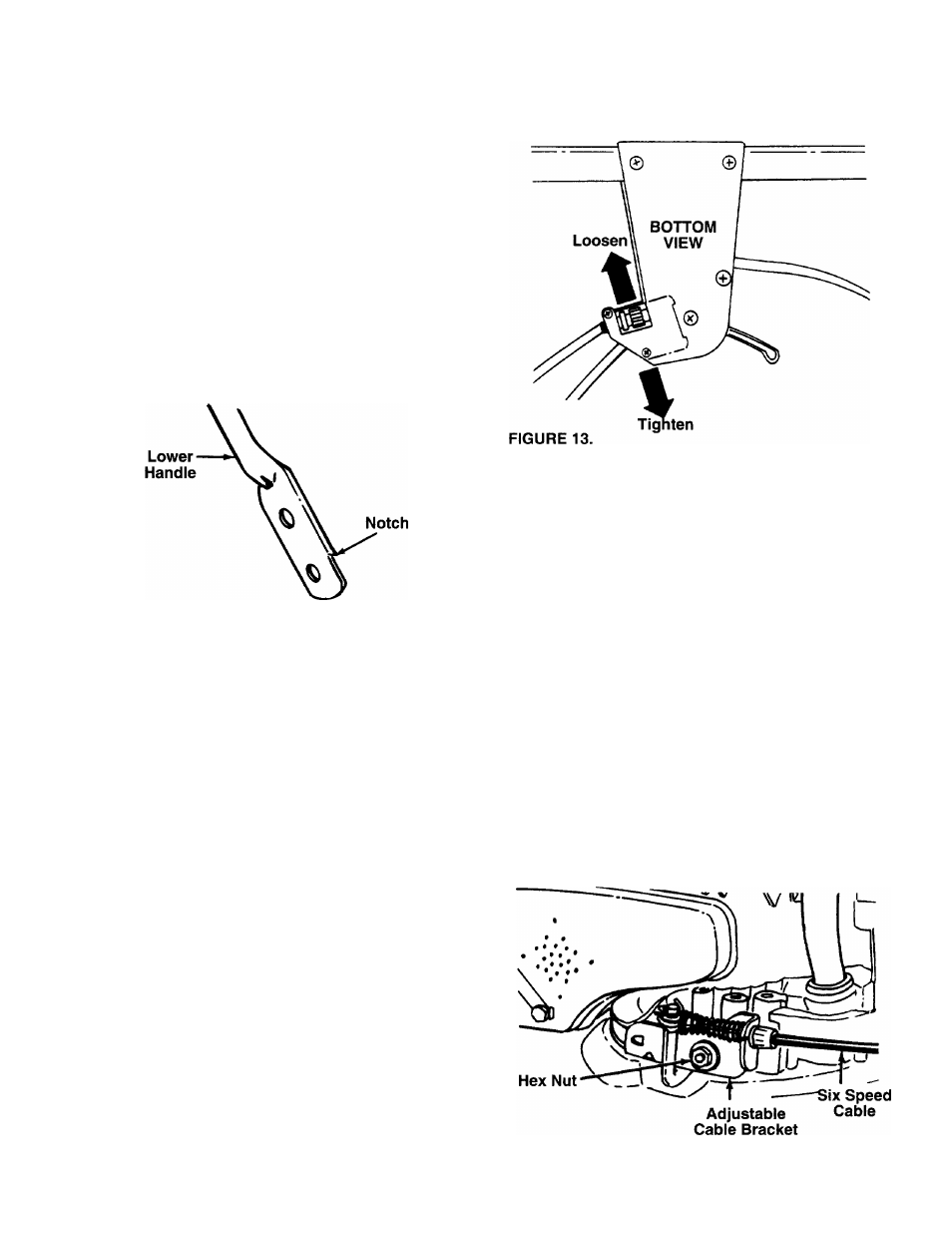
DRIVE CLUTCH ADJUSTMENT
The correct drive clutch adjustment varies
speed of the mower. The drive clutch adjustn
be checked as follows. Without starting the
engage the drive clutch control (squeeze con
against the handle) and pull the mower b£
The wheels should lock. Then release the dri'
control and pull the mower backward. It shot
freely (or with only a small amount of resistan
If the wheels lock up when pulled backward
drive clutch control released (engine off), or
moves forward with the drive clutch control
(engine running), turn the adjustment wheel
beneath the drive clutch control housing, to’
operator to loosen the cable. See figure 13.
the adjustment as instructed above.
If the mower does not drive in low speed, tic
cable by turning the adjustment wheel away
operator. Recheck the adjustment.
Periodic adjustment may also be necessar
normal stretch and wear on the belt. Adjustn
be needed if the wheels seem to hesitate,
engine maintains the same speed. To tigi
cable, move the adjustment wheel toward t
Always be certain to recheck the adjustment.
with the
ent may
engine,
rol lever
ckward.
'e clutch
Id move
;e).
with the
f mower
eleased
located
\rard the
^echeck
hten the
from the
' due to
ent may
but the
iten the
ie right.
SIX SPEED SHIFT ADJUSTMENT
Periodic adjustment may be required due to normal
wear. Adjustment is needed if the shift lever cannot
be moved to all six positions.
• Loosen the nut which secures the adjustable cable
bracket, located on the left side of the engine. See
figure 14.
• Place the shift lever in high speed (6) position.
• Move the bracket to make certain it is loose. Then
slide it towards the rear of the unit as far as it will
go, so that the pulley halves (beneath the deck) are
against each other. Make certain the belt does not
interfere.
•
Tighten the nut to secure the bracket in this
position.
FIGURE 14.
14