Sears 486.24412 User Manual
Page 9
Attention! The text in this document has been recognized automatically. To view the original document, you can use the "Original mode".
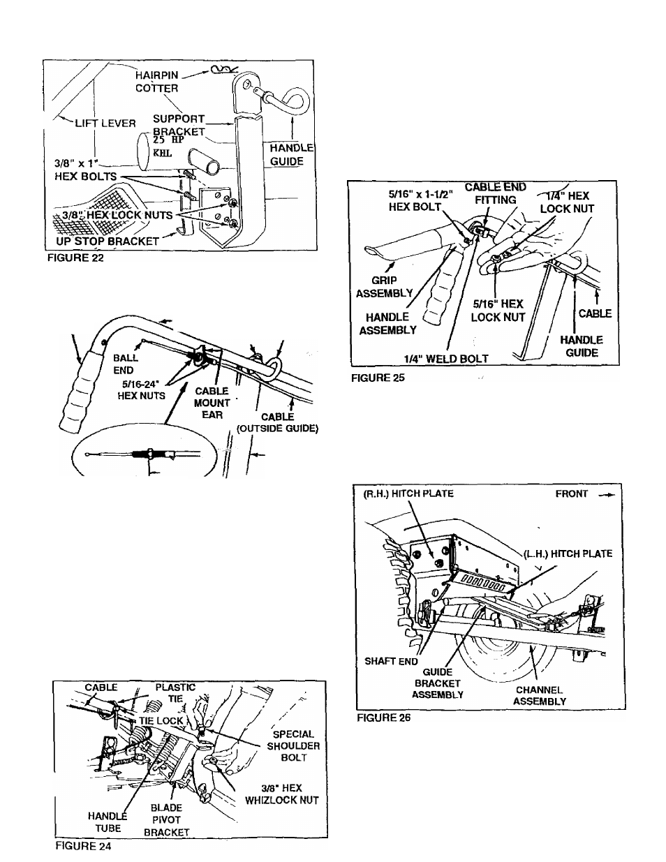
23.
Assemble handle guide (with loop outside) at
top of support bracket and secure with one hairpin
cotter inside. See figures 22 and 23,
HANDLE
GRIP
HANDLE
J^SSY
HAtRPtN HANDLE
COTTER GUIDE
3/4“ J
CONTROLCABLE END
SUPPORT
BRACKET
FIGURE 23
24. Assemble handle assembly down through handle
guide as shown in figure 23. Secure lower end of
handle to top side of blade pivcS bracket with
special shoulder bolt (on top) and 3/8" hex whiziock
nut underneath. See figure 24,
25. Assemble one 5/16-24" hex nut onto threaded
end of control cable approximately 3/4" from end.
Assemble threaded end of cable up through cable
mount ear and secure with second 5/16-24" hex
nut. See figure 24.
26. Assemble handle grip on upper end of handle
assembly if not already pre-assembled. See
figure 23,
27. Wrap plastic tie around handle tube and cable,
{see figure 24), assembling end of tie through
lock. Pull plastic tie tight to retain cable to handle
tube near front of tractor hood. Cut off extra
plastic end.
28. Assemble grip assembly to handle assembly us
ing one 5/16" X 1-1/2" hex bolt and one 5/16" hex
lock nut. NOTE: Do not over tighten lock nut,
grip assembly must pivot freely.
29. Assemble ball end of cable (see figure 23), through
round hole in cable end fitting and into slot of
fitting. See figure 25. Assemble cable end fitting
over 1/4* weld bolt on grip assembly and secure
with one 1/4" hex lock nut. NOTE: Do not over
tighten lock nut, cable fitting must pivot freely.
30. Assemble guide bracket assembly shaft end into
the left hand hitch plate. See figure 26. Slide
guide assembly back to the right and into the hole
in the right hand hitch plate, and secure with a
hairpin cotter on each end. See figure 27, Lower
front end of guide bracket assembly to straddle
channel assembly. See figure 27.